Wiper And Washer System (W/ Rain Sensor) Wiper And Washer Switch Circuit
DESCRIPTION
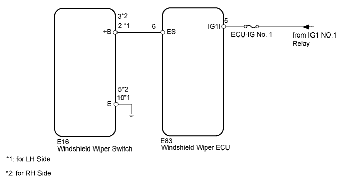
WIRING DIAGRAM
INSPECTION PROCEDURE
INSPECT FUSE (ECU-IG No. 1)
READ VALUE USING INTELLIGENT TESTER (WINDSHIELD WIPER SWITCH)
CHECK HARNESS AND CONNECTOR (WINDSHIELD WIPER SWITCH - BATTERY AND BODY GROUND)
WIPER AND WASHER SYSTEM (w/ Rain Sensor) - Wiper and Washer Switch Circuit |
DESCRIPTION
This circuit provides power to operate the windshield wiper switch. The manual operation signals are sent to the windshield wiper ECU.
WIRING DIAGRAM
INSPECTION PROCEDURE
| 1.INSPECT FUSE (ECU-IG No. 1) |
Remove the ECU-IG No. 1 fuse from the cowl side junction block LH.
Measure the resistance according to the value(s) in the table below.
- Standard Resistance:
Tester Connection
| Condition
| Specified Condition
|
ECU-IG No. 1 fuse
| Always
| Below 1 Ω
|
| 2.READ VALUE USING INTELLIGENT TESTER (WINDSHIELD WIPER SWITCH) |
Check the Data List for proper functioning of the windshield wiper switch.
Combination SwitchTester Display
| Measurement Item/Range
| Normal Condition
| Diagnostic Note
|
F Wiper LO SW
| Front wiper LO switch / ON or OFF
| ON: Front wiper switch in LO
OFF: Front wiper switch not in LO
| -
|
F Wiper HI SW
| Front wiper HI switch / ON or OFF
| ON: Front wiper switch in HI
OFF: Front wiper switch not in HI
| -
|
F Wiper AUTO SW
| Front wiper AUTO switch / ON or OFF
| ON: Front wiper switch in AUTO
OFF: Front wiper switch not in AUTO
| -
|
F Wiper MIST SW
| Front wiper MIST switch / ON or OFF
| ON: Front wiper switch in MIST
OFF: Front wiper switch not in MIST
| -
|
F Washer SW
| Front washer switch / ON or OFF
| ON: Front washer switch on
OFF: Front washer switch off
| -
|
- OK:
- The display is as specified in the normal condition.
| OK |
|
|
|
| PROCEED TO NEXT SUSPECTED AREA SHOWN IN PROBLEM SYMPTOMS TABLE (Click here) |
|
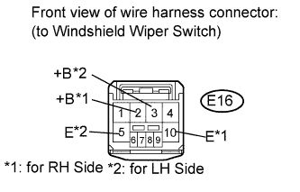
| 3.CHECK HARNESS AND CONNECTOR (WINDSHIELD WIPER SWITCH - BATTERY AND BODY GROUND) |
Disconnect the E16 switch connector.
Measure the voltage according to the value(s) in the table below.
- Standard Voltage:
for LH SideTester Connection
| Switch Condition
| Specified Condition
|
E16-2 (+B) - Body ground
| Engine switch on (IG)
| 11 to 14 V
|
E16-2 (+B) - Body ground
| Engine switch off
| Below 1 V
|
for RH SideTester Connection
| Switch Condition
| Specified Condition
|
E16-3 (+B) - Body ground
| Engine switch on (IG)
| 11 to 14 V
|
E16-3 (+B) - Body ground
| Engine switch off
| Below 1 V
|
Measure the resistance according to the value(s) in the table below.
- Standard Resistance:
for LH SideTester Connection
| Condition
| Specified Condition
|
E16-10 (E) - Body ground
| Always
| Below 1 Ω
|
for RH SideTester Connection
| Condition
| Specified Condition
|
E16-5 (E) - Body ground
| Always
| Below 1 Ω
|
| | REPAIR OR REPLACE HARNESS OR CONNECTOR |
|
|