Wiper And Washer System (W/ Rain Sensor) Headlight Signal Circuit
DESCRIPTION
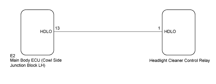
WIRING DIAGRAM
INSPECTION PROCEDURE
CHECK LOW BEAM HEADLIGHTS OPERATION
CHECK HARNESS AND CONNECTOR (HEADLIGHT CLEANER CONTROL RELAY - MAIN BODY ECU)
CHECK MAIN BODY ECU (COWL SIDE JUNCTION BLOCK LH)
WIPER AND WASHER SYSTEM (w/ Rain Sensor) - Headlight Signal Circuit |
DESCRIPTION
The headlight cleaner control relay detects the low beam headlights status.
WIRING DIAGRAM
INSPECTION PROCEDURE
| 1.CHECK LOW BEAM HEADLIGHTS OPERATION |
Check that the low beam headlights operate normally (Click here).
- OK:
- Low beam headlights operate normally.
| 2.CHECK HARNESS AND CONNECTOR (HEADLIGHT CLEANER CONTROL RELAY - MAIN BODY ECU) |
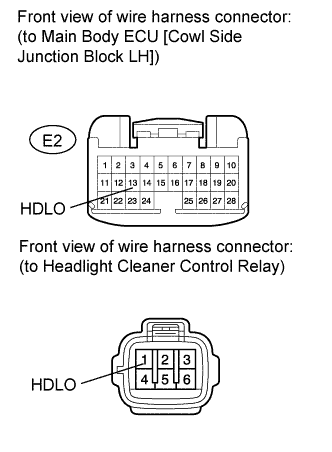
Disconnect the E2 main body ECU (cowl side junction block LH) connector.
Disconnect the headlight cleaner control relay connector.
Measure the resistance according to the value(s) in the table below.
- Standard Resistance:
Tester Connection
| Condition
| Specified Condition
|
1 (HDLO) - E2-13 (HDLO)
| Always
| Below 1 Ω
|
1 (HDLO) - Body ground
| Always
| 10 kΩ or higher
|
| | REPAIR OR REPLACE HARNESS OR CONNECTOR |
|
|
| 3.CHECK MAIN BODY ECU (COWL SIDE JUNCTION BLOCK LH) |
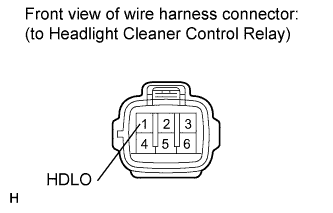
Disconnect the headlight cleaner control relay connector.
Measure the voltage according to the value(s) in the table below.
- Standard Voltage:
Tester Connection
| Switch Condition
| Specified Condition
|
1 (HDLO) - Body ground
| Engine switch on (IG)
Headlight dimmer switch in HEAD
| 11 to 14 V
|
1 (HDLO) - Body ground
| Engine switch on (IG)
Headlight dimmer switch not in HEAD
| Below 1 V
|
| | REPLACE MAIN BODY ECU (COWL SIDE JUNCTION BLOCK LH) |
|
|
| OK |
|
|
|
| PROCEED TO NEXT SUSPECTED AREA SHOWN IN PROBLEM SYMPTOMS TABLE (Click here) |
|