Power Back Door System -- Terminals Of Ecu |
| CHECK POWER BACK DOOR UNIT ASSEMBLY (POWER BACK DOOR ECU) |
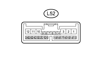 |
Disconnect the L52 power back door unit assembly (power back door ECU) connector.
Measure the voltage and resistance according to the value(s) in the table below.
If the result is not as specified, there may be a malfunction on the wire harness side.Terminal No. (Symbol) Wiring Color Terminal Description Condition Specified Condition L52-10 (ECUB) - Body ground R - Body ground ECUB power supply Always 11 to 14 V L52-12 (B) - Body ground B - Body ground Power supply Always 11 to 14 V L52-8 (IG) - Body ground G - Body ground IG power supply Engine switch on (IG) 11 to 14 V L52-8 (IG) - Body ground G - Body ground IG power supply Engine switch off Below 1 V L52-15 (OSL) - L52-14 (OSE) G - BR*1
G - BE*2Power back door sensor LH circuit Power back door sensor LH not pressed Approximately 1 kΩ L52-15 (OSL) - L52-14 (OSE) G - BR*1
G - BE*2Power back door sensor LH circuit Power back door sensor LH pressed Below 100 Ω L52-13 (OSR) - L52-14 (OSE) Y - BR*1
P - BE*2Power back door sensor RH circuit Power back door sensor RH not pressed Approximately 1 kΩ L52-13 (OSR) - L52-14 (OSE) Y - BR*1
P - BE*2Power back door sensor RH circuit Power back door sensor RH pressed Below 100 Ω L52-11 (GND) - Body ground W-B - Body ground Body ground Always Below 1 Ω L52-17 (MSW) - Body ground G - Body ground Power back door main switch signal circuit Power back door main switch not pushed (on) Below 1 Ω L52-17 (MSW) - Body ground G - Body ground Power back door main switch signal circuit Power back door main switch pushed (off) 10 kΩ or higher L52-4 (DS1) - Body ground R - Body ground Back door control switch signal circuit Back door control switch on Below 1 Ω L52-4 (DS1) - Body ground R - Body ground Back door control switch signal circuit Back door control switch off 10 kΩ or higher Reconnect the L52 power back door unit assembly (power back door ECU) connector.
Measure the voltage according to the value(s) in the table below.
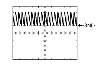
Terminal No. (Symbol) Wiring Color Terminal Description Condition Specified Condition L52-26 (BZR+) - Body ground L - Body ground Power back door warning buzzer signal input Power back door warning buzzer sounding Pulse generation
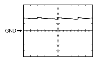
(See waveform 1)L52-26 (BZR+) - Body ground L - Body ground Power back door warning buzzer signal input Power back door warning buzzer stopped Below 1 V L52-2 (DC+) - L52-1 (DC-) R - B Power back door lock motor circuit Power back door lock motor operating 11 to 14 V L52-2 (DC+) - L52-1 (DC-) R - B Power back door lock motor circuit Power back door lock motor stopped Below 1 V L52-17 (MSW) - Body ground G - Body ground Power back door main switch signal circuit Power back door main switch not pushed (on) Below 1 V L52-17 (MSW) - Body ground G - Body ground Power back door main switch signal circuit Power back door main switch pushed (off) Pulse generation
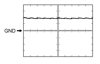
(See waveform 2)L52-20 (FUL) - Body ground W - Body ground Back door courtesy switch signal circuit Back door opened Below 1 V L52-20 (FUL) - Body ground W - Body ground Back door courtesy switch signal circuit Back door closed Pulse generation
(See waveform 3)L52-4 (DS1) - Body ground R - Body ground Back door control switch signal circuit Back door control switch on Below 1 V L52-4 (DS1) - Body ground R - Body ground Back door control switch signal circuit Back door control switch off Pulse generation
(See waveform 4)L52-22 (HAF) - Body ground G - Body ground Back door lock half-latch switch signal circuit Back door opened Below 1 V L52-22 (HAF) - Body ground G - Body ground Back door lock half-latch switch signal circuit Back door closed Pulse generation
(See waveform 5)L52-24 (POS) - Body ground B - Body ground Back door lock position switch signal circuit Back door closed Below 1 V L52-24 (POS) - Body ground B - Body ground Back door lock position switch signal circuit Back door opened Pulse generation
(See waveform 6)L52-23 (CYLH) - Body ground G - Body ground Lower tail gate courtesy switch LH circuit Lower tail gate opened Below 1 V L52-23 (CYLH) - Body ground G - Body ground Lower tail gate courtesy switch LH circuit Lower tail gate closed Pulse generation
(See waveform 7)L52-7 (CYRH) - Body ground Y - Body ground*1
P - Body ground*2Lower tail gate courtesy switch RH circuit Lower tail gates opened Below 1 V L52-7 (CYRH) - Body ground Y - Body ground*1
P - Body ground*2Lower tail gate courtesy switch RH circuit Lower tail gate closed Pulse generation
(See waveform 8)- *1: Model code: GRJ200L-GNANKC, URJ202L-GNTEKC
- *2: Model code except: GRJ200L-GNANKC, URJ202L-GNTEKC
- *1: Model code: GRJ200L-GNANKC, URJ202L-GNTEKC
Using an oscilloscope, check waveform 1.
Waveform 1 (Reference) Item Content Terminal (Symbol) L52-26 (BZR+) - Body ground Tool Setting 5 V/DIV., 1 ms/DIV Condition Power back door warning buzzer sounding Using an oscilloscope, check waveform 2.
Waveform 2 (Reference) Item Content Terminal (Symbol) L52-17 (MSW) - Body ground Tool Setting 5 V/DIV., 10 ms/DIV Condition Power back door main switch pushed (off) Using an oscilloscope, check waveform 3.
Waveform 3 (Reference) Item Content Terminal (Symbol) L52-20 (FUL) - Body ground Tool Setting 5 V/DIV., 10 ms/DIV Condition Back door closed Using an oscilloscope, check waveform 4.
Waveform 4 (Reference) Item Content Terminal (Symbol) L52-4 (DS1) - Body ground Tool Setting 5 V/DIV., 10 ms/DIV Condition Back door lock control switch off Using an oscilloscope, check waveform 5.
Waveform 5 (Reference) Item Content Terminal (Symbol) L52-22 (HAF) - Body ground Tool Setting 5 V/DIV., 10 ms/DIV Condition Back door closed Using an oscilloscope, check waveform 6.
Waveform 6 (Reference) Item Content Terminal (Symbol) L52-24 (POS) - Body ground Tool Setting 5 V/DIV., 10 ms/DIV Condition Back door opened Using an oscilloscope, check waveform 7.
Waveform 7 (Reference) Item Content Terminal (Symbol) L52-23 (CYLH) - Body ground Tool Setting 5 V/DIV., 10 ms/DIV Condition Lower tail gate closed Using an oscilloscope, check waveform 8.
Waveform 8 (Reference) Item Content Terminal (Symbol) L52-7 (CYRH) - Body ground Tool Setting 5 V/DIV., 10 ms/DIV Condition Lower tail gate closed
 |
 |
|
|
|
|
|
|
| CHECK MAIN BODY ECU (COWL SIDE JUNCTION BLOCK LH) |

Disconnect the 2A, 2B, 2D, E2 and E3 main body ECU (cowl side junction block LH) connectors.
Measure the voltage and resistance according to the value(s) in the table below.
If the result is not as specified, there may be a malfunction in the wire harness.Terminal No. (Symbol) Wiring Color Terminal Description Condition Specified Condition 2B-20 (BATB) - Body ground L - Body ground Battery power supply Always 11 to 14 V 2A-1 (ACC) - Body ground B - Body ground ACC power supply Always 11 to 14 V E2-2 (PBDS) - Body ground R - Body ground Door control switch circuit Door control switch pushed (on) Below 1 Ω E2-2 (PBDS) - Body ground R - Body ground Door control switch circuit Door control switch not pushed (off) 10 kΩ or higher 2D-62 (GND2) - Body ground W-B - Body ground Ground Always Below 1 Ω E3-1 (GND3) - Body ground BR - Body ground Ground Always Below 1 Ω Reconnect the 2A, 2B, 2D, E2 and E3 ECU (cowl side junction block LH) connectors.
Measure the voltage according to the value(s) in the table below.
Terminal No. (Symbol) Wiring Color Terminal Description Condition Specified Condition E2-2 (PBDS) - Body ground R - Body ground Door control switch circuit Door control switch pushed (on) Below 1 V E2-2 (PBDS) - Body ground R - Body ground Door control switch circuit Door control switch not pushed (off) Pulse generation
(See waveform 1 or 2)Using an oscilloscope, check waveform.
Waveform1 (Reference) Item Content Terminal (Symbol) E2-2 (PBDS) - Body ground Tool Setting 5 V/DIV., 10 ms/DIV Condition Door control switch not pushed (off) Using an oscilloscope, check waveform.
Waveform2 (Reference) Item Content Terminal (Symbol) E2-2 (PBDS) - Body ground Tool Setting 5 V/DIV., 10 ms/DIV Condition Door control switch not pushed (off)
 |
 |