Sliding Roof System Sliding Roof Ecu Power Source Circuit
DESCRIPTION
WIRING DIAGRAM
INSPECTION PROCEDURE
READ VALUE USING INTELLIGENT TESTER (IGNITION SWITCH SIGNAL)
INSPECT FUSE (S/ROOF, ECU-IG NO. 2)
CHECK HARNESS AND CONNECTOR (SLIDING ROOF DRIVE GEAR - BATTERY AND BODY GROUND)
SLIDING ROOF SYSTEM - Sliding Roof ECU Power Source Circuit |
DESCRIPTION
If the sliding function and tilt function do not operate, there may be a malfunction in the sliding roof ECU power source circuit.
WIRING DIAGRAM
INSPECTION PROCEDURE
| 1.READ VALUE USING INTELLIGENT TESTER (IGNITION SWITCH SIGNAL) |
Use the Data List to check if the ignition switch signal is functioning properly (Click here).
Sliding RoofTester Display
| Test Part
| Control Range
| Diagnostic Note
|
Ignition (MPX)
| Ignition switch signal (MPX signal)/ON or OFF
| ON: Engine switch on (IG)
OFF: Engine switch off
| -
|
Ignition (Direct Signal)
| Ignition switch signal/ON or OFF
| ON: Engine switch on (IG)
OFF: Engine switch off
| -
|
- OK:
- The intelligent tester displays as shown in the table according to the operation of each switch.
| OK |
|
|
|
| REPLACE SLIDING ROOF DRIVE GEAR SUB-ASSEMBLY (SLIDING ROOF ECU) (Click here) |
|
| 2.INSPECT FUSE (S/ROOF, ECU-IG NO. 2) |
Remove the S/ROOF and ECU-IG NO. 2 fuses from the main body ECU.
Measure the resistance according to the value(s) in the table below.
- Standard Resistance:
Tester Connection
| Condition
| Specified Condition
|
S/ROOF fuse
| Always
| Below 1 Ω
|
ECU-IG NO. 2 fuse
| Always
| Below 1 Ω
|
| 3.CHECK HARNESS AND CONNECTOR (SLIDING ROOF DRIVE GEAR - BATTERY AND BODY GROUND) |
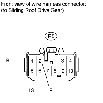
Disconnect the R5 drive gear connector.
Measure the resistance and voltage according to the value(s) in the table below.
- Standard Resistance:
Tester Connection
| Condition
| Specified Condition
|
R5-2 (E) - Body ground
| Always
| Below 1 Ω
|
- Standard Voltage:
Tester Connection
| Switch Condition
| Specified Condition
|
R5-1 (B) - Body ground
| Always
| 11 to 14 V
|
R5-5 (IG) - Body ground
| Engine switch off
| Below 1 V
|
R5-5 (IG) - Body ground
| Engine switch on (IG)
| 11 to 14 V
|
| | REPAIR OR REPLACE HARNESS OR CONNECTOR |
|
|
| OK |
|
|
|
| REPLACE SLIDING ROOF DRIVE GEAR SUB-ASSEMBLY (SLIDING ROOF ECU) (Click here) |
|