Land Cruiser URJ200 URJ202 GRJ200 VDJ200 - 1VD-FTV ENGINE MECHANICAL
DRIVE BELT - INSTALLATION
| 1. INSTALL V-RIBBED BELT |
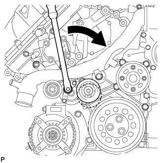
Attach a wrench to the V-ribbed belt tensioner bracket and turn the wrench clockwise.

Install the V-ribbed belt as shown in the illustration.
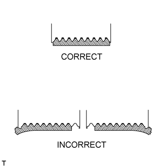
Check that the belt fits properly in the ribbed grooves.
- HINT:
- Check with your hand to confirm that the belt has not slipped out of the groove on the bottom of the pulley.
- If it has slipped out, replace the V-ribbed belt. Install a new V-ribbed belt.
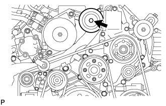
| 2. INSTALL NO. 3 IDLER PULLEY (w/ Viscous Heater) |

Align the No. 3 idler pulley bracket knock pin and No. 1 idler pulley bracket knock pin hole and install the No. 3 idler pulley with the nut.
- Torque:
- 88 N*m{ 898 kgf*cm, 64 ft.*lbf}
| 3. INSTALL NO. 1 IDLER PULLEY (w/ Viscous Heater) |
Install the collar, No. 1 idler pulley and cover with the bolt.
- Torque:
- 49 N*m{ 495 kgf*cm, 36 ft.*lbf}
| 4. INSTALL V-RIBBED BELT (w/ Viscous Heater) |

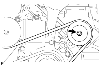
Install the V-ribbed belt as shown in the illustration.
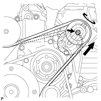
Temporarily install the lock nut, and turn the bolt clockwise.
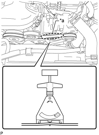
Using a belt tension gauge, inspect the belt tension.
- Standard Belt Tension:
Item Condition Specified Condition New belt 5 to 35°C (41 to 95°F) 550 to 800 N (56 to 82 kgf, 123.6 to 179.8 lbf) Used belt 5 to 35°C (41 to 95°F) 300 to 500 N (31 to 51 kgf, 67.4 to 112.4 lbf)
| *a | Measuring Point |
- HINT:
Tighten the nut.
- Torque:
- 40 N*m{ 408 kgf*cm, 30 ft.*lbf}
Check that the belt fits properly in the ribbed grooves.
- HINT:
- Check with your hand to confirm that the belt has not slipped out of the groove on the bottom of the pulley.
- If it has slipped out, replace the V-ribbed belt. Install a new V-ribbed belt.
| 5. INSTALL INTAKE AIR CONNECTOR |
Connect the intake air connector to the No. 1 and No. 2 air cleaner pipes.
Install the connector with the 2 bolts.
- Torque:
- 21 N*m{ 214 kgf*cm, 15 ft.*lbf}
Tighten the 2 hose clamps.
- Torque:
- 6.3 N*m{ 64 kgf*cm, 56 in.*lbf}
Attach the 3 wire harness clamps.
w/o Viscous Heater:
Connect the connector to the water temperature sensor.
w/ Viscous Heater:
Connect the 2 connectors to the water temperature sensor and viscous with magnet clutch heater.
| 6. TEMPORARILY INSTALL NO. 1 AIR CLEANER HOSE |
Temporarily install the air cleaner hose to the intake air connector.
| 7. INSTALL AIR CLEANER CAP SUB-ASSEMBLY |
Connect the air cleaner cap to the air cleaner hose, and install the air cleaner cap with the 4 clamps.
Connect the mass air flow meter connector and attach the wire harness clamp to the air cleaner cap.
Attach the wire harness clamp.
Align the protrusion of the air cleaner cap and the concave portion of the air cleaner hose.
Tighten the 2 hose clamps.
- Torque:
- 2.5 N*m{ 25 kgf*cm, 22 in.*lbf}
| 8. INSTALL NO. 1 ENGINE COVER SUB-ASSEMBLY (w/ Intercooler) |

Install the engine cover with the 2 nuts.
- Torque:
- 8.0 N*m{ 82 kgf*cm, 71 in.*lbf}
| 9. INSTALL UPPER RADIATOR SUPPORT SEAL |
Install the upper radiator support seal with the 7 clips.
| 10. INSTALL NO. 1 ENGINE UNDER COVER SUB-ASSEMBLY |
Install the No. 1 engine under cover with the 10 bolts.
- Torque:
- 29 N*m{ 296 kgf*cm, 21 ft.*lbf}
| 11. INSTALL FRONT FENDER SPLASH SHIELD SUB-ASSEMBLY RH |
Install the front fender splash shield RH with the clip, and then install the 3 bolts and 2 screws.
| 12. INSTALL FRONT FENDER SPLASH SHIELD SUB-ASSEMBLY LH |
Install the front fender splash shield LH with the clip, and then install the 3 bolts and screw.