Air Conditioning Panel (W/ Navigation System) -- Removal |
- HINT:
- Use the same procedures for the LHD vehicle and RHD vehicle.
- The procedures listed below are for the LHD vehicle.
| 1. PRECAUTION |
- NOTICE:
- After turning the ignition switch off, waiting time may be required before disconnecting the cable from the battery terminal. Therefore, make sure to read the disconnecting the cable from the battery terminal notice before proceeding with work (Click here).
| 2. DISCONNECT CABLE FROM NEGATIVE BATTERY TERMINAL |
- NOTICE:
- When disconnecting the cable, some systems need to be initialized after the cable is reconnected (Click here).
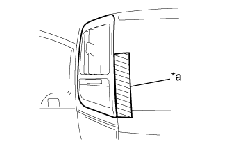
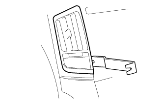
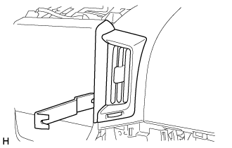
| 3. REMOVE NO. 1 SPEAKER OPENING COVER ASSEMBLY |
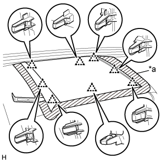 |
Put protective tape around the No. 1 speaker opening cover assembly.
Text in Illustration *a Protective Tape
Using a moulding remover A, detach the 8 clips and remove the No. 1 speaker opening cover assembly.
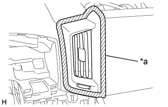
| 4. REMOVE NO. 3 INSTRUMENT PANEL REGISTER ASSEMBLY |
for Type A:
Put protective tape around the No. 3 instrument panel register assembly.
Text in Illustration *a Protective Tape Using moulding remover B, raise the No. 3 instrument panel register assembly.
Pull the No. 3 instrument panel register assembly by hand to detach the 7 claws and guide and remove the No. 3 instrument panel register assembly.
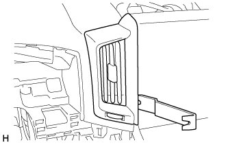
for Type B:
Put protective tape around the No. 3 instrument panel register assembly.
Text in Illustration *a Protective Tape Using moulding remover B, raise the No. 3 instrument panel register assembly.
Pull the No. 3 instrument panel register assembly by hand to detach the 6 claws and remove the No. 3 instrument panel register assembly.
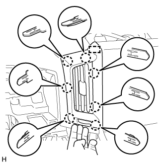
| 5. REMOVE NO. 4 INSTRUMENT PANEL REGISTER ASSEMBLY |
for Type A:
Put protective tape around the No. 3 instrument panel register assembly.
Text in Illustration *a Protective Tape Using moulding remover B, raise the No. 3 instrument panel register assembly.
Pull the No. 3 instrument panel register assembly by hand to detach the 7 claws and guide and remove the No. 3 instrument panel register assembly.
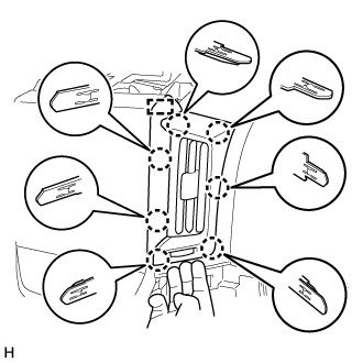
for Type B:
Put protective tape around the No. 3 instrument panel register assembly.
Text in Illustration *a Protective Tape Using moulding remover B, raise the No. 3 instrument panel register assembly.
Pull the No. 3 instrument panel register assembly by hand to detach the 6 claws and remove the No. 3 instrument panel register assembly.
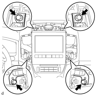
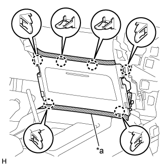
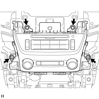
| 6. REMOVE MULTI-DISPLAY ASSEMBLY |
Remove the 2 screws and 2 bolts.
 |
Pull the multi-display assembly to detach the 3 clips and 4 claws on the backside of the multi-display assembly.
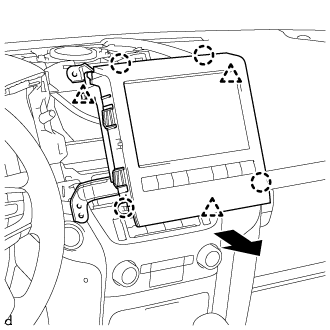 |
Disconnect the connectors and remove the multi-display assembly.
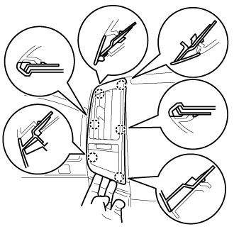
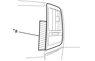
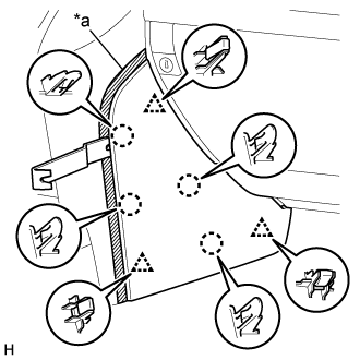
| 7. REMOVE NO. 2 INSTRUMENT PANEL FINISH PANEL CUSHION |
for Type A:
Put protective tape around the No. 2 instrument panel finish panel cushion.
Text in Illustration *a Protective Tape Using a moulding remover B, detach the 4 claws and 3 clips and remove the No. 2 instrument panel finish panel cushion.
for Type B:
Put protective tape around the No. 2 instrument panel finish panel cushion.
Text in Illustration *a Protective Tape Using a moulding remover, detach the 7 claws and remove the No. 2 instrument panel finish panel cushion.
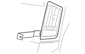
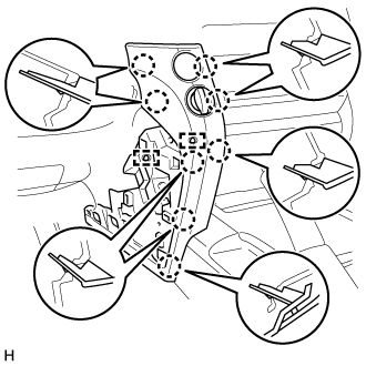
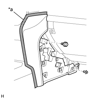
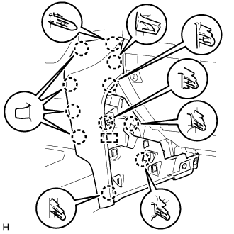
| 8. REMOVE LOWER INSTRUMENT PANEL PAD SUB-ASSEMBLY LH |
for Type A:
Put protective tape around the lower instrument panel pad sub-assembly LH.
Text in Illustration *a Protective Tape Remove the clip and screw.
Detach the 11 claws and guide.
Disconnect the connector and detach the clamps and remove the lower instrument panel pad sub-assembly LH.
for Type B:
Put protective tape around the lower instrument panel pad sub-assembly LH.
Text in Illustration *a Protective Tape Remove the clip and screw.
Detach the 8 claws and 2 guides and remove the lower instrument panel pad sub-assembly LH.
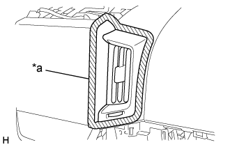
| 9. REMOVE NO. 1 INSTRUMENT PANEL FINISH PANEL CUSHION |
for Type A:
Put protective tape around the No. 1 instrument panel finish panel cushion.
Text in Illustration *a Protective Tape Using a moulding remover B, detach the 4 claws and 3 clips and remove the No. 2 instrument panel finish panel cushion.
for Type B:
Put protective tape around the No. 1 instrument panel finish panel cushion.
Text in Illustration *a Protective Tape Using a moulding remover, detach the 7 claws and remove the No. 2 instrument panel finish panel cushion.
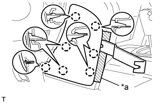
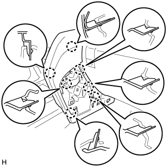
| 10. REMOVE LOWER INSTRUMENT PANEL PAD SUB-ASSEMBLY RH |
for Type A:
Put protective tape around the lower instrument panel pad sub-assembly RH.
Text in Illustration *a Protective Tape Remove the clip and screw.
Detach the 11 claws and guide and remove the lower instrument panel pad sub-assembly RH.
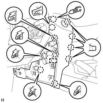
for Type B:
Put protective tape around the lower instrument panel pad sub-assembly RH.
Text in Illustration *a Protective Tape Remove the clip and screw.
Detach the 7 claws and remove the lower instrument panel pad sub-assembly RH.
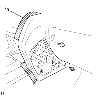
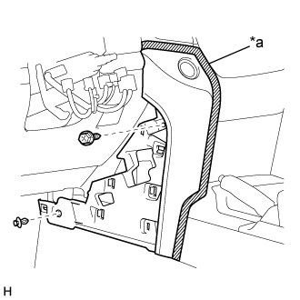
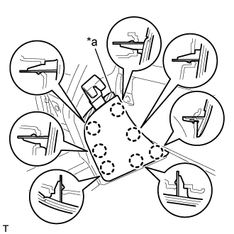
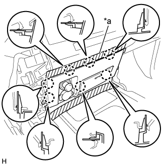
| 11. REMOVE LOWER CENTER INSTRUMENT CLUSTER FINISH PANEL SUB-ASSEMBLY |
for Type A:
Put protective tape around the lower center instrument cluster finish panel sub-assembly.
Text in Illustration *a Protective Tape Detach the 6 claws and remove the lower center instrument cluster finish panel sub-assembly.
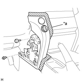
for Type B:
Put protective tape around the lower center instrument cluster finish panel sub-assembly.
Text in Illustration *a Protective Tape Detach the 7 claws.
Disconnect the connectors and remove the lower center instrument cluster finish panel sub-assembly.
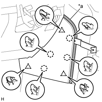
| 12. REMOVE MULTI-MEDIA MODULE RECEIVER ASSEMBLY |
 |
Remove the 2 bolts and 2 screws.
Pull the multi-media module receiver assembly to detach the 5 claws on the backside of the multi-media module receiver assembly.
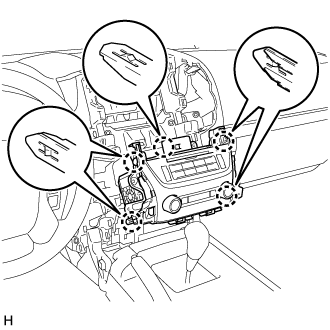 |
Disconnect each connector and remove the multi-media module receiver assembly.