Dtc B1442 Air Inlet Damper Control Servo Motor Circuit
DESCRIPTION
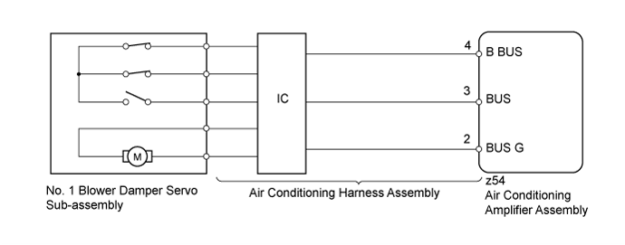
WIRING DIAGRAM
INSPECTION PROCEDURE
READ VALUE USING INTELLIGENT TESTER (AIR INLET DAMPER TARG PULSE)
CHECK NO. 1 BLOWER DAMPER SERVO SUB-ASSEMBLY
CHECK AIR CONDITIONING HARNESS ASSEMBLY
DTC B1442 Air Inlet Damper Control Servo Motor Circuit |
DESCRIPTION
The No. 1 blower damper servo sub-assembly sends pulse signals to inform the air conditioning amplifier assembly of the damper position. The air conditioning amplifier assembly activates the motor (normal or reverse) based on the signals to move the air inlet damper to any position, which controls the intake air settings (fresh, fresh/recirculation and recirculation).- HINT:
- Confirm that no mechanical problem is present because this trouble code may be stored when either a damper link or damper is mechanically locked.
DTC Code
| DTC Detection Condition
| Trouble Area
|
B1442
| The air inlet damper position does not change for 30 seconds or more when the air conditioning amplifier assembly operates the No. 1 blower damper servo sub-assembly.
| - No. 1 blower damper servo sub-assembly
- Air conditioning harness assembly
- Air conditioning amplifier assembly
|
WIRING DIAGRAM
INSPECTION PROCEDURE
| 1.READ VALUE USING INTELLIGENT TESTER (AIR INLET DAMPER TARG PULSE) |
Use the Data List to check if the No. 1 blower damper servo sub-assembly is functioning properly (Click here).
Air ConditionerTester Display
| Measurement Item/Range
| Normal Condition
| Diagnostic Note
|
Air Inlet Damper Targ Pulse
| No. 1 blower damper servo sub-assembly target pulse / Min.: 0, Max.: 255
| for LHD - Recirculation: 37 (pulse)
- Fresh: 9 (pulse)
for RHD - Recirculation: 9 (pulse)
- Fresh: 37 (pulse)
| -
|
- OK:
- The display is as specified in the normal condition column.
ResultResult
| Proceed to
|
OK (When troubleshooting according to the DTC)
| A
|
OK (When troubleshooting according to problem symptoms table)
| B
|
NG
| C
|
| | PROCEED TO NEXT SUSPECTED AREA SHOWN IN PROBLEM SYMPTOMS TABLE (Click here) |
|
|
| | REPLACE AIR CONDITIONING AMPLIFIER ASSEMBLY (Click here) |
|
|
| 2.CHECK NO. 1 BLOWER DAMPER SERVO SUB-ASSEMBLY |
Temporarily replace the No. 1 blower damper servo sub-assembly (Click here).
- HINT:
- Since the No. 1 blower damper servo sub-assembly cannot be inspected while it is removed from the vehicle, replace the No. 1 blower damper servo sub-assembly with a new or normally functioning one.
Clear the DTCs (Click here).
Check for DTCs (Click here).
ResultResult
| Proceed to
|
DTC B1442 is not output
| A
|
DTC B1442 is output
| B
|
| A |
|
|
|
| END (NO. 1 BLOWER DAMPER SERVO SUB-ASSEMBLY IS FAULTY) |
|
| 3.CHECK AIR CONDITIONING HARNESS ASSEMBLY |
Temporarily replace the air conditioning harness assembly with a new or normally functioning one.
- for LHD: Click here.
- for RHD: Click here.
Clear the DTCs (Click here).
Check for DTCs (Click here).
ResultResult
| Proceed to
|
DTC B1442 is not output
| A
|
DTC B1442 is output
| B
|
| | REPLACE AIR CONDITIONING AMPLIFIER ASSEMBLY (Click here) |
|
|
| A |
|
|
|
| END (AIR CONDITIONING HARNESS ASSEMBLY IS FAULTY) |
|