Dtc B1488/88 Rear Air Mix Damper Control Servo Motor Circuit On Front Passenger Side
DESCRIPTION
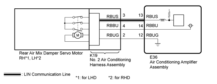
WIRING DIAGRAM
INSPECTION PROCEDURE
READ VALUE USING GTS (A/M SERVO TARG PULSE [REAR P], A/M SERVO ACTUAL PULSE [REAR P]) (REAR AIR MIX DAMPER SERVO MOTOR)
CHECK HARNESS AND CONNECTOR (NO. 2 AIR CONDITIONING HARNESS ASSEMBLY- AIR CONDITIONING AMPLIFIER ASSEMBLY)
CHECK REAR AIR MIX DAMPER SERVO MOTOR
CHECK NO. 2 AIR CONDITIONING HARNESS ASSEMBLY
CHECK FOR DTC
DTC B1488/88 Rear Air Mix Damper Control Servo Motor Circuit on Front Passenger Side |
DESCRIPTION
- *1: for LHD
- *2: for RHD
The rear air mix damper servo motor RH*1 or LH*2 sends pulse signals to indicate the damper position to the air conditioning amplifier assembly. The air conditioning amplifier assembly activates the motor (normal or reverse) based on these signals to move the rear air mix damper to the appropriate position. This adjusts the amount of air passing through the heater core after passing the evaporator and controls the temperature of the blown air.- HINT:
- Confirm that no mechanical problem is present because this trouble code can be output when either a damper link or damper is mechanically locked.
DTC Code
| DTC Detection Condition
| Trouble Area
|
B1488/88
| The rear air mix damper position does not change even if the air conditioning amplifier assembly operates the air mix damper servo motor RH*1 or LH*2.
| - Rear air mix damper servo motor RH*1
- Rear air mix damper servo motor LH*2
- No. 2 air conditioning harness assembly
- Harness or connector
- Air conditioning amplifier assembly
|
WIRING DIAGRAM
INSPECTION PROCEDURE
| 1.READ VALUE USING GTS (A/M SERVO TARG PULSE [REAR P], A/M SERVO ACTUAL PULSE [REAR P]) (REAR AIR MIX DAMPER SERVO MOTOR) |
- *1: for LHD
- *2: for RHD
Use the Data List to check if the mode damper servo motor RH*1 or LH*2 is functioning properly (Click here).
Air ConditionerTester Display
| Measurement Item/Range
| Normal Condition
| Diagnostic Note
|
A/M Servo Targ Pulse (Rear P)
| Rear air mix damper servo motor RH*1 or LH*2 target pulse / Min.: 128, Max.: 383
| for LHD: - MAX COLD: 181 (pulse)
- MAX HOT: 136 (pulse)
for RHD: - MAX COOL: 137 (pulse)
- MAX HOT: 182 (pulse)
| - Displayed between 136 and 181 pulse
- Rear air mix damper servo motor RH system malfunction (for LHD)
- Rear air mix damper servo motor LH system malfunction (for RHD)
|
A/M Servo Actual Pulse (Rear P)
| Rear air mix damper servo motor RH*1 or LH*2 target pulse / Min.: 128, Max.: 383
| for LHD: - MAX COLD: 181 (pulse)
- MAX HOT: 136 (pulse)
for RHD: - MAX COLD: 137 (pulse)
- MAX HOT: 182 (pulse)
| - Displayed between 136 and 181 pulse
- Rear air mix damper servo motor RH system malfunction (for LHD)
- Rear air mix damper servo motor LH system malfunction (for RHD)
|
- OK:
- When the rear temperature adjustment switch for front passenger side is turned from MAX COLD to MAX HOT, the actual pulse changes following the target pulse.
ResultResult
| Proceed to
|
Target pulse changes but actual pulse does not change
| A
|
Target pulse and actual pulse do not change
| B
|
Actual pulse changes following the target pulse (When troubleshooting according to the DTC)
| C
|
Actual pulse changes following the target pulse (When troubleshooting according to Problem Symptoms Table)
| D
|
| | REPLACE AIR CONDITIONING AMPLIFIER ASSEMBLY (Click here) |
|
|
| |
|
| | PROCEED TO NEXT SUSPECTED AREA SHOWN IN PROBLEM SYMPTOMS TABLE (Click here) |
|
|
| 2.CHECK HARNESS AND CONNECTOR (NO. 2 AIR CONDITIONING HARNESS ASSEMBLY- AIR CONDITIONING AMPLIFIER ASSEMBLY) |
Disconnect the K19 No. 2 air conditioning harness assembly connector.
Disconnect the E36 air conditioning amplifier assembly connector.
Measure the resistance according to the value(s) in the table below.
- Standard Resistance:
Tester Connection
| Condition
| Specified Condition
|
K19-2 (RBUG) - E36-12 (RBUG)
| Always
| Below 1 Ω
|
K19-3 (RBUS) - E36-13 (RBUS)
| Always
| Below 1 Ω
|
K19-4 (RBBU) - E36-14 (RBBU)
| Always
| Below 1 Ω
|
K19-2 (RBUG) or E36-12 (RBUG) - Body ground
| Always
| 10 kΩ or higher
|
K19-3 (RBUS) or E36-13 (RBUS) - Body ground
| Always
| 10 kΩ or higher
|
K19-4 (RBBU) or E36-14 (RBBU) - Body ground
| Always
| 10 kΩ or higher
|
| | REPAIR OR REPLACE HARNESS OR CONNECTOR |
|
|
| 3.CHECK REAR AIR MIX DAMPER SERVO MOTOR |
Replace the rear air mix damper servo motor RH*1 or LH*2 (Click here).
- *1: for LHD
- *2: for RHD
- HINT:
- Since the servo motor cannot be inspected while it is removed from the vehicle, replace the servo motor with a normal one.
Clear the DTCs (Click here).
Check for DTCs (Click here).
- OK:
- DTC B1488/88 is not output.
| | REPLACE AIR CONDITIONING AMPLIFIER ASSEMBLY (Click here) |
|
|
| OK |
|
|
|
| END (REAR DAMPER SERVO MOTOR [for Front Passenger Side] WAS DEFECTIVE) |
|
| 4.CHECK NO. 2 AIR CONDITIONING HARNESS ASSEMBLY |
Replace the No. 2 air conditioning harness assembly with new or known good one (Click here).
Clear the DTCs (Click here).
Check for DTCs (Click here).
- OK:
- DTC B1488/88 is not output.
| | REPLACE AIR CONDITIONING AMPLIFIER ASSEMBLY (Click here) |
|
|
| OK |
|
|
|
| END (NO. 2 AIR CONDITIONING HARNESS ASSEMBLY WAS DEFECTIVE) |
|
Clear the DTCs (Click here).
Check for DTCs (Click here).
- OK:
- DTC B1488/88 is not output.
| | REPLACE AIR CONDITIONING AMPLIFIER ASSEMBLY (Click here) |
|
|