Dtc B1422/22 Compressor Lock Sensor Circuit
SYSTEM DESCRIPTION
WIRING DIAGRAM
INSPECTION PROCEDURE
INSPECT MAGNET CLUTCH ASSEMBLY
CHECK AIR CONDITIONING AMPLIFIER ASSEMBLY
INSPECT COOLER COMPRESSOR ASSEMBLY
CHECK HARNESS AND CONNECTOR (AIR CONDITIONING AMPLIFIER ASSEMBLY -
COOLER COMPRESSOR ASSEMBLY)
DTC B1422/22 Compressor Lock Sensor Circuit |
SYSTEM DESCRIPTION
The ECM sends the engine speed signal to the air conditioning amplifier assembly via CAN communication.The air conditioning amplifier assembly reads the difference between compressor speed and engine speed. When the difference becomes too large, the air conditioning amplifier assembly determines that the compressor is locked, and turns the magnetic clutch off.DTC Code
| DTC Detection Condition
| Trouble Area
|
B1422/22
| An open or short in the compressor lock sensor circuit.
| - CAN communication line
- Cooler compressor assembly
- Harness or connector
- Air conditioning amplifier assembly
|
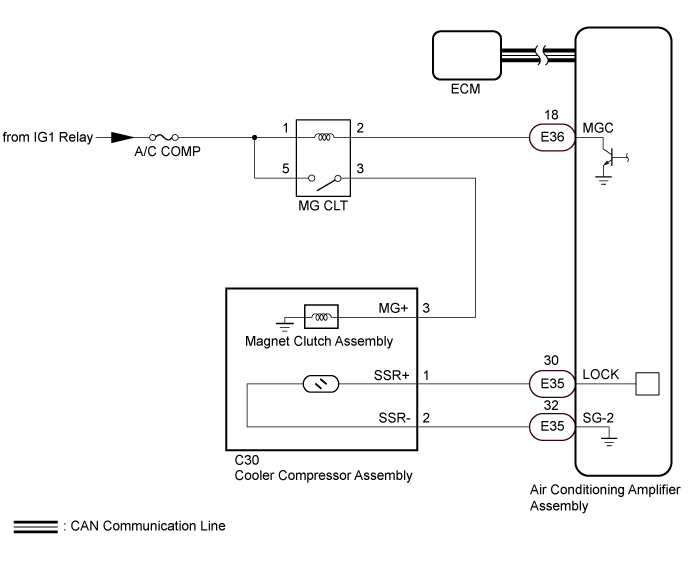
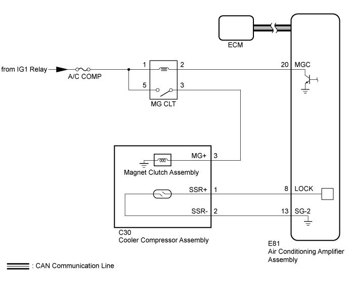
WIRING DIAGRAM
INSPECTION PROCEDURE
- NOTICE:
- ECM malfunctions can affect the storage of this DTC. Therefore, check all ECM DTCs and confirm that the system is normal before performing the following inspection.
- for 1GR-FE: Click here
- for 1VD-FTV (w/ DPF): Click here
- for 1VD-FTV (w/o DPF): Click here
- for 1UR-FE: Click here
- for 3UR-FE: Click here
- The air conditioning system uses the CAN communication system. Inspect the communication function by following How to Proceed with Troubleshooting (Click here ).
| 1.INSPECT MAGNET CLUTCH ASSEMBLY |
Remove the magnet clutch assembly.
- for 1GR-FE: Click here
- for 1VD-FTV: Click here
- for 1UR-FE: Click here
- for 3UR-FE: Click here
Inspect the magnet clutch assembly.
- for 1GR-FE: Click here
- for 1VD-FTV: Click here
- for 1UR-FE: Click here
- for 3UR-FE: Click here
ResultResult
| Proceed to
|
OK
| A
|
NG (for 1GR-FE)
| B
|
NG (for 1VD-FTV)
| C
|
NG (for 1UR-FE)
| D
|
NG (for 3UR-FE)
| E
|
| 2.CHECK AIR CONDITIONING AMPLIFIER ASSEMBLY |
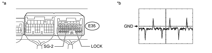
w/ Rear Heater:
Remove the air conditioning amplifier assembly with its connectors still connected (Click here).
Text in Illustration*a
| Component with harness connected
((Air Conditioning Amplifier Assembly)
| *b
| Waveform
|
Measure the waveform of the connector.
Measurement ConditionItem
| Contents
|
Terminal No. (Symbol)
| E35-30 (LOCK) - E35-32 (SG-2)
|
Tool Setting
| 200 mV/DIV., 10 ms/DIV.
|
Condition
| - Engine idling
- A/C switch on
- Blower switch LO
|
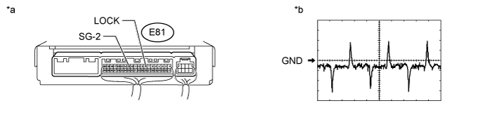
w/o Rear Heater:
Text in Illustration*a
| Component with harness connected
((Air Conditioning Amplifier Assembly)
| *b
| Waveform
|
Remove the air conditioning amplifier assembly with its connectors still connected (Click here).
Measure the waveform of the connector.
Measurement ConditionItem
| Contents
|
Terminal No. (Symbol)
| E81-8 (LOCK) - E81-13 (SG-2)
|
Tool Setting
| 200 mV/DIV., 10 ms/DIV.
|
Condition
| Engine running
A/C switch on
Blower switch LO
|
| OK |
|
|
|
| REPLACE AIR CONDITIONING AMPLIFIER ASSEMBLY (Click here) |
|
| 3.INSPECT COOLER COMPRESSOR ASSEMBLY |
Remove the cooler compressor assembly.
- for 1GR-FE: Click here
- for 1VD-FTV: Click here
- for 1UR-FE: Click here
- for 3UR-FE: Click here
Inspect the cooler compressor assembly.
- for 1GR-FE: Click here
- for 1VD-FTV: Click here
- for 1UR-FE: Click here
- for 3UR-FE: Click here
ResultResult
| Proceed to
|
OK
| A
|
NG (for 1GR-FE)
| B
|
NG (for 1VD-FTV)
| C
|
NG (for 1UR-FE)
| D
|
NG (for 3UR-FE)
| E
|
| 4.CHECK HARNESS AND CONNECTOR (AIR CONDITIONING AMPLIFIER ASSEMBLY -
COOLER COMPRESSOR ASSEMBLY) |
w/ Rear Heater:
Disconnect the E35 air conditioning amplifier assembly connector.
Disconnect the C30 cooler compressor assembly connector.
Measure the resistance according to the value(s) in the table below.
- Standard Resistance:
Tester Connection
| Condition
| Specified Condition
|
E35-30 (LOCK) - C30-1 (SSR+)
| Always
| Below 1 Ω
|
E35-32 (SG-2) - C30-2 (SSR-)
| Always
| Below 1 Ω
|
C30-1 (SSR+) - C30-2 (SSR-)
| Always
| 10 kΩ or higher
|
E35-30 (LOCK) or C30-1 (SSR+) - Body ground
| Always
| 10 kΩ or higher
|
E35-32 (SG-2) or C30-2 (SSR-) - Body ground
| Always
| 10 kΩ or higher
|
w/o Rear Heater:
Disconnect the E81 air conditioning amplifier assembly connector.
Disconnect the C30 cooler compressor assembly connector.
Measure the resistance according to the value(s) in the table below.
- Standard Resistance:
Tester Connection
| Condition
| Specified Condition
|
E81-8 (LOCK) - C30-1 (SSR+)
| Always
| Below 1 Ω
|
E81-13 (SG-2) - C30-2 (SSR-)
| Always
| Below 1 Ω
|
C30-1 (SSR+) - C30-2 (SSR-)
| Always
| Below 1 Ω
|
E81-8 (LOCK) or C30-1 (SSR+) - Body ground
| Always
| 10 kΩ or higher
|
E81-13 (SG-2) or C30-2 (SSR-) - Body ground
| Always
| 10 kΩ or higher
|
| | REPAIR OR REPLACE HARNESS OR CONNECTOR |
|
|
| OK |
|
|
|
| REPLACE AIR CONDITIONING AMPLIFIER ASSEMBLY (Click here) |
|