Vehicle Interior. Land Cruiser. Urj200, 202 Grj200 Vdj200
Heating Air Conditioning. Land Cruiser. Urj200, 202 Grj200 Vdj200
Air Conditioning System (For Automatic Air Conditioning System) -- System Description |
| GENERAL |
The air conditioning system has the following features:
- The 4-ZONE air conditioner system controls the temperature of the front and rear seats independently. In addition, it uses the amount of sunlight and temperature of each seat to adjust the temperature and airflow volume. When the 4-ZONE switch is on, the temperature, the airflow mode and airflow volume of each of the 4 seats (driver, front passenger, rear left, rear right) are automatically adjusted.
- The 2-ZONE air conditioner system controls the temperature of the left and right seats independently, and sets the temperature for the driver seat and front passenger seat. In addition, it uses the amount of sunlight and temperature of the left and right seats to adjust the temperature and airflow volume.
When the 2-ZONE switch is on, the temperature, airflow mode and airflow volume of the driver seat and front passenger seat are automatically adjusted. - In accordance with the temperature set using the temperature control switch, the air conditioning amplifier assembly determines the outlet temperature based on the input signals from various sensors. In addition, corrections are made in accordance with the signals from the water temperature sensor to control the outlet air temperature.
- Controls the blower motor in accordance with the airflow volume determined by the air conditioning amplifier assembly based on the input signals from various sensors.
- Automatically changes the outlets in accordance with the outlet mode ratio that is determined by the air conditioning amplifier assembly based on the input signals from various sensors.
- Based on the signals from the ambient temperature sensor, this system calculates the outside temperature and indicates it in the multi-information display in the combination meter.
- For vehicles with the rear air conditioner, there are rear side and roof side air ducts, and independent temperature and airflow mode adjustments are automatically performed.
- The Positive Temperature Coefficient (PTC) heater system contains a PTC heater that heats the air that has passed through the heater core to ensure proper heater performance.
- A compact, lightweight, and highly efficient straight flow (full-path flow) aluminum heater core is used.
- The micro dust and pollen filter control is used to remove pollen in the air around the upper areas of the driver and front passenger seats.
- The air conditioning amplifier assembly is equipped with a self diagnosis function. If there is a malfunction in the system, it stores the DTCs (Diagnostic Trouble Codes) in its memory.
- The 4-ZONE air conditioner system controls the temperature of the front and rear seats independently. In addition, it uses the amount of sunlight and temperature of each seat to adjust the temperature and airflow volume. When the 4-ZONE switch is on, the temperature, the airflow mode and airflow volume of each of the 4 seats (driver, front passenger, rear left, rear right) are automatically adjusted.
| MODE POSITION AND DAMPER OPERATION |

| Control Damper | Operation Position | Damper Position | Operation |
| Air Inlet Control Damper | Fresh | A | Brings in fresh air. |
| Recirculation | B | Recirculates internal air. | |
| Air Mix Control Damper | Max Cool to Max Hot | K, L, M | Varies the mixture ratio of cold air and hot air in order to regulate the temperature continuously from hot to cool. |
| Cool Air Bypass Control Damper | Max Cool to Max Hot | H, I, J | Cool air blows out from the front center register and side registers in order to adjust the temperature around the heads of the occupants during cooling or warming. |
| Mode Control Damper |  Def | C | Defrosts the windshield through the center defroster. |
 Foot/Def | D | Defrosts the windshield through the center defroster and side defroster while air is also blown out from the front and rear footwell register ducts. In addition, air blows out slightly from the front and rear center registers and side register. | |
 Foot | E | Air blows out of the front and rear footwell register duct, front and rear center register and side register. In addition, air blows out slightly from the center defroster and side defroster. | |
 Bi - Level | F | Air blows out of the center registers, side register, and rear center register to defrost the windshield. Air also blows out from the front and rear footwell register ducts. | |
 Face | G | Air blows out of the center registers and side registers to defrost the windshield. |

| Control Damper | Operation Position | Damper Position | Operation |
| Mode Control Damper | Face | A | Air blows out of the rear roof side register. |
Bi - Level | B | Air blows out of the rear roof side register and rear footwell register. | |
Foot | C | Air blows out of the rear footwell register. | |
| Air Mix Control Damper | Max Cool to Max Hot | D, E | Varies the mixture ratio of cold air and hot air in order to regulate the temperature continuously from hot to cool. |
| AIR OUTLETS AND AIRFLOW VOLUME |

| Air Outlet Mode | Selectable Mode | Register | Register Duct | Defroster | |||||
| Automatic | Manual | Center | Side | Front Foot | Rear Face | Rear Foot | |||
| A | B | C | D | E | F | ||||
| FACE-U*1 | ○ | ○ |  | | - |  | - | - |
| FACE-L*2, *6 | ○ | - | | |  | | - | - | |
| B/L-U*1 | ○ | ○ | | |  | | | - |
| B/L*2 | ○ | - | | | | | | - | |
| FOOT F*3 | ○ | - | | | |  | | |
| FOOT R*4 | ○ | ○ | | | | | | | |
| FOOT D*5 | ○ | - | | | | | | | |
| F/D | ○ | ○ | | | | | | |
| DEF | ○ | ○ | - | - | - | - | - | |
- HINT:
- The size of the circle indicates the proportion of airflow volume.
- *1: Greater airflow volume at the upper area.
- *2: Greater airflow volume at the lower area.
- *3: Greater airflow volume at the front.
- *4: Greater airflow volume at the rear foot.
- *5: Greater airflow volume at the defroster.
- *6: In contrast to FACE-U, a small amount of air comes out of the front footwell register duct.
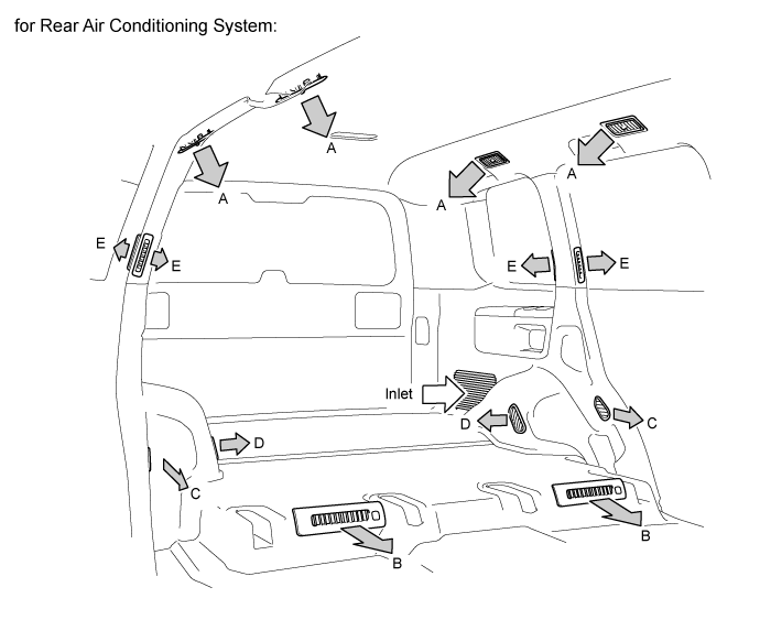
| Air Outlet Mode | Register Duct | |||||
| Roof | Rear Foot 1 | Rear Side 2 | Rear Foot 2 | C Pillar | ||
| A | B | C | D | E | ||
| FACE | | - | - | - | - |
| BI-LEVEL | | | | | |
| FOOT | - | | | | |
- HINT:
- The size of the circle indicates the proportion of airflow volume.