Dtc B14C0 Front Right Seat Heat Sensor Circuit
Seat. Land Cruiser. Urj200, 202 Grj200 Vdj200
DESCRIPTION
WIRING DIAGRAM
INSPECTION PROCEDURE
CLEAR DTC
CHECK FOR DTC
READ VALUE USING GTS (FR SEAT HEATER TEMPERATURE)
INSPECT FRONT SEAT CUSHION HEATER ASSEMBLY RH
INSPECT SEAT HEATER CONTROL SUB-ASSEMBLY RH
CHECK HARNESS AND CONNECTOR (AIR CONDITIONING AMPLIFIER ASSEMBLY - SEAT HEATER CONTROL SUB-ASSEMBLY RH)
DTC B14C0 Front Right Seat Heat Sensor Circuit |
DESCRIPTION
Output to the front seat cushion heater assembly RH temperature sensor stops if one of the following occurs: 1) the temperature sensor is open or shorted; or 2) the temperature sensor is damaged and its output value does not change.DTC Code
| DTC Detection Condition
| Trouble Area
|
B14C0
| Seat heater temperature sensor malfunction
| - Air conditioning amplifier assembly
- Front seat cushion heater assembly RH
- Seat heater control sub-assembly RH
- Wire harness or connector
|
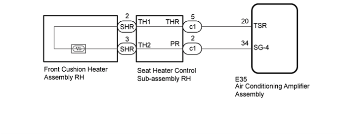
WIRING DIAGRAM
INSPECTION PROCEDURE
Clear the DTCs (Click here).
Check for DTCs (Click here).
- OK:
- DTC B14C0 is not output.
| 3.READ VALUE USING GTS (FR SEAT HEATER TEMPERATURE) |
Connect the GTS to the DLC3.
Turn the engine switch on (IG).
Turn the GTS on.
Enter the following menus: Body Electrical / Air Conditioner / Data List.
Read the Data List according to the display on the GTS.
Air ConditionerTester Display
| Measurement Item/Display
| Range
| Normal Condition
| Diagnostic Note
|
FR Seat Heater Temperature
| Front seat RH heater temperature
| -29.7°C to 59.55°C
| Within range from 32 to 43°C (89 to 109°F)
| Front seat heater is on
|
| OK |
|
|
|
| REPLACE AIR CONDITIONING AMPLIFIER ASSEMBLY (Click here) |
|
| 4.INSPECT FRONT SEAT CUSHION HEATER ASSEMBLY RH |
Remove the front seat cushion heater assembly RH (Click here).
Inspect the front seat cushion heater assembly RH (Click here).
| | REPLACE FRONT SEAT CUSHION HEATER ASSEMBLY RH (Click here) |
|
|
| 5.INSPECT SEAT HEATER CONTROL SUB-ASSEMBLY RH |
Remove the seat heater control sub-assembly RH (Click here).
Measure the resistance according to the value(s) in the table below.
- Standard Resistance:
Tester Connection
| Condition
| Specified Condition
|
c1-5 (THR) - SHR-2 (TH1)
| Always
| Below 1 Ω
|
c1-2 (PR) - SHR-3 (TH2)
| Always
| Below 1 Ω
|
c1-5 (THR) or SHR-2 (TH1) - Body ground
| Always
| 10 kΩ or higher
|
c1-2 (PR) or SHR-3 (TH2) - Body ground
| Always
| 10 kΩ or higher
|
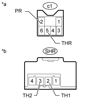
Text in Illustration*a
| Seat Heater Control Sub-assembly RH
(to Air Conditioning Amplifier Assembly)
|
*b
| Seat Heater Control Sub-assembly RH
(to Front Seat Cushion Heater Assembly RH)
|
| | REPLACE SEAT HEATER CONTROL SUB-ASSEMBLY RH (Click here) |
|
|
| 6.CHECK HARNESS AND CONNECTOR (AIR CONDITIONING AMPLIFIER ASSEMBLY - SEAT HEATER CONTROL SUB-ASSEMBLY RH) |
Disconnect the E35 air conditioning amplifier assembly connector.
Disconnect the c1 seat heater control sub-assembly RH connector.
Measure the resistance according to the value(s) in the table below.
- Standard Resistance:
Tester Connection
| Condition
| Specified Condition
|
c1-5 (THR) - E35-34 (SG-4)
| Always
| Below 1 Ω
|
c1-5 (THR) or E35-34 (SG-4) - Body ground
| Always
| 10 kΩ or higher
|
c1-5 (THR) - E35-34 (TSR)
| Always
| Below 1 Ω
|
c1-5 (THR) or E35-34 (TSR) - Body ground
| Always
| 10 kΩ or higher
|
| | REPAIR OR REPLACE HARNESS OR CONNECTOR |
|
|
| OK |
|
|
|
| REPLACE AIR CONDITIONING AMPLIFIER ASSEMBLY (Click here) |
|