Front Power Seat Control System (W/ Seat Position Memory System) Power Seat Position Is Not Memorized
Seat. Land Cruiser. Urj200, 202 Grj200 Vdj200
DESCRIPTION
WIRING DIAGRAM
INSPECTION PROCEDURE
CHECK FRONT POWER SEAT CONTROL FUNCTION
READ VALUE USING GTS (SEAT MEMORY SWITCH)
PERFORM ACTIVE TEST USING GTS (BUZZER)
REPLACE OUTER MIRROR CONTROL ECU ASSEMBLY
CHECK SEAT MEMORY SWITCH FUNCTION
INSPECT SEAT MEMORY SWITCH
CHECK HARNESS AND CONNECTOR (OUTER MIRROR CONTROL ECU ASSEMBLY - SEAT MEMORY SWITCH)
FRONT POWER SEAT CONTROL SYSTEM (w/ Seat Position Memory System) - Power Seat Position is not Memorized |
DESCRIPTION
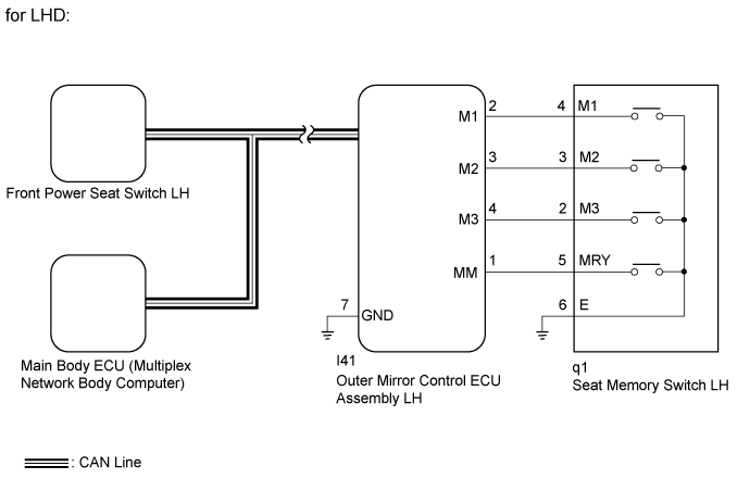
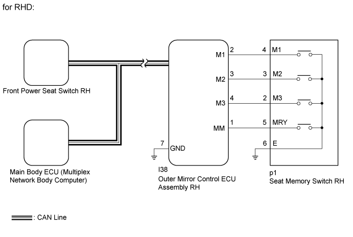
The main body ECU (multiplex network body ECU) receives seat memory switch signals from the outer mirror control ECU assembly LH*1, RH*2 via CAN communication. If the SET switch is being pressed when one of the M1, M2 or M3 switches is pressed, or if one of the M1, M2 or M3 switches is pressed within 3 seconds of pressing the SET switch, the main body ECU (multiplex network body ECU) sends an memory request signal to the front power seat switch LH*1, RH*2. After receiving the request signal, the front power seat switch LH*1, RH*2 memorizes the location data of each motor.1*: for LHD2*: for RHD
WIRING DIAGRAM
INSPECTION PROCEDURE
- NOTICE:
- The seat position will not be stored if the SET switch and 2 or more of the seat memory switches (for example, M1 switch and M2 switch) are pressed simultaneously.
If a memorizing operation has failed, release all of the switches. The seat memory function will not operate unless the switches are released.
- The seat will not return to the memorized position if 2 or more of the seat memory switches (for example, M1 switch and M2 switch) are pressed simultaneously.
If a restoring operation has failed, release all of the switches. The seat memory function will not operate unless the switches are released.
- The front power seat control system uses the CAN communication system. First, confirm that there are no malfunctions in the CAN communication system. Refer to How to Proceed with Troubleshooting (Click here).
- Before replacing the main body ECU (multiplex network body ECU), refer to the Entry and Start System (for Entry Function) (Click here).
| 1.CHECK FRONT POWER SEAT CONTROL FUNCTION |
Check that each function of the power seat operates normally by using the front power seat switches (Click here).
- OK:
- Each function of power seat operates normally by using seat switches.
| 2.READ VALUE USING GTS (SEAT MEMORY SWITCH) |
Check the Data List for proper functioning of the seat memory switch LH*1, RH*2 (Click here).
- *1: for LHD
- *2: for RHD
MirrorTester Display
| Measurement Item/Range
| Normal Condition
| Diagnostic Note
|
SET Switch
| Seat memory SET switch signal / ON or OFF
| ON: Seat memory SET switch on
OFF: Seat memory SET switch off
| -
|
M1 Switch
| Seat memory switch 1 signal / ON or OFF
| ON: Seat memory switch 1 on
OFF: Seat memory switch 1 off
| -
|
M2 Switch
| Seat memory switch 2 signal / ON or OFF
| ON: Seat memory switch 2 on
OFF: Seat memory switch 2 off
| -
|
M3 Switch
| Seat memory switch 3 signal / ON or OFF
| ON: Seat memory switch 3 on
OFF: Seat memory switch 3 off
| -
|
- OK:
- On the GTS screen, each item changes between ON and OFF according to above chart.
| 3.PERFORM ACTIVE TEST USING GTS (BUZZER) |
Connect the GTS to the DLC3.
Turn the engine switch on (IG).
Turn the GTS on.
Enter the following menus: Body Electrical / Driver Seat / Active Test.
Perform the Active Test according to the display on the GTS.
- Driver Seat:
Tester Display
| Measurement Item
| Control Range
| Diagnostic Note
|
Buzzer
| Buzzer operation
| OFF/ON
| -
|
- OK:
- Buzzer sounds normally.
| 4.REPLACE OUTER MIRROR CONTROL ECU ASSEMBLY |
Replace the outer mirror control ECU assembly LH*1, RH*2 with a new or known good one (Click here).
*1: for LHD
*2: for RHD
| 5.CHECK SEAT MEMORY SWITCH FUNCTION |
Perform a memory operation properly (Click here).
- NOTICE:
- The seat position will not be recorded if the seat memory SET switch and 2 or more of the seat memory switches (for example, seat memory switch 1 and seat memory switch 2) are pressed simultaneously.
- If a memorizing operation has failed, release all switches. The seat memory function does not operate unless the switches are released.
- OK:
- Seat memory switch function operates normally.
| OK |
|
|
|
| END (OUTER MIRROR CONTROL ECU ASSEMBLY WAS DEFECTIVE) |
|
| 6.INSPECT SEAT MEMORY SWITCH |
*1: for LHD*2: for RHDRemove the seat memory switch LH*1, RH*2 (Click here).
Inspect the seat memory switch LH*1, RH*2 (Click here).
| 7.CHECK HARNESS AND CONNECTOR (OUTER MIRROR CONTROL ECU ASSEMBLY - SEAT MEMORY SWITCH) |
*1: for LHD*2: for RHDDisconnect the I41*1, I38*2 ECU connector.
Disconnect the q1*1, p1*2 switch connector.
Measure the resistance according to the value(s) in the table below.
- Standard Resistance:
for LHD:Tester Connection
| Condition
| Specified Condition
|
I41-2 (M1) - q1-4 (M1)
| Always
| Below 1 Ω
|
I41-3 (M2) - q1-3 (M2)
| Always
| Below 1 Ω
|
I41-4 (M3) - q1-2 (M3)
| Always
| Below 1 Ω
|
I41-1 (MM) - q1-5 (MRY)
| Always
| Below 1 Ω
|
I41-7 (GND) - Body ground
| Always
| Below 1 Ω
|
q1-6 (E) - Body ground
| Always
| Below 1 Ω
|
I41-2 (M1) - Body ground
| Always
| 10 kΩ or higher
|
I41-3 (M2) - Body ground
| Always
| 10 kΩ or higher
|
I41-4 (M3) - Body ground
| Always
| 10 kΩ or higher
|
I41-1 (MM) - Body ground
| Always
| 10 kΩ or higher
|
I41-7 (GND) - Body ground
| Always
| 10 kΩ or higher
|
for RHD:Tester Connection
| Condition
| Specified Condition
|
I38-2 (M1) - p1-4 (M1)
| Always
| Below 1 Ω
|
I38-3 (M2) - p1-3 (M2)
| Always
| Below 1 Ω
|
I38-4 (M3) - p1-2 (M3)
| Always
| Below 1 Ω
|
I38-1 (MM) - p1-5 (MRY)
| Always
| Below 1 Ω
|
I38-7 (GND) - Body ground
| Always
| Below 1 Ω
|
p1-6 (E) - Body ground
| Always
| Below 1 Ω
|
I38-2 (M1) - Body ground
| Always
| 10 kΩ or higher
|
I38-3 (M2) - Body ground
| Always
| 10 kΩ or higher
|
I38-4 (M3) - Body ground
| Always
| 10 kΩ or higher
|
I38-1 (MM) - Body ground
| Always
| 10 kΩ or higher
|
I38-7 (GND) - Body ground
| Always
| 10 kΩ or higher
|
| | REPAIR OR REPLACE HARNESS OR CONNECTOR |
|
|
| OK |
|
|
|
| REPLACE OUTER MIRROR CONTROL ECU ASSEMBLY (Click here) |
|