Land Cruiser URJ200 URJ202 GRJ200 VDJ200 - 1UR-FE ENGINE MECHANICAL
CAMSHAFT - REMOVAL
| 1. REMOVE TIMING CHAIN COVER SUB-ASSEMBLY |
()
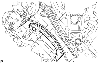
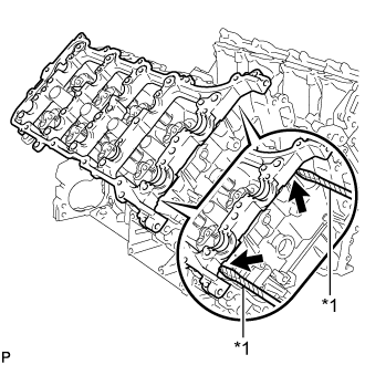
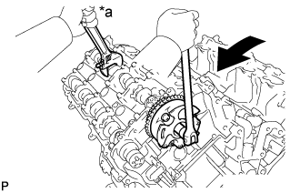
| 2. SET NO. 1 CYLINDER TO TDC/COMPRESSION |
Temporarily install the pulley set bolt.
Rotate the crankshaft clockwise so that the timing marks on the crankshaft timing gear and camshaft timing gears are as shown in the illustration.
- HINT:
- If the timing marks do not align, rotate the crankshaft clockwise again and align the timing marks.
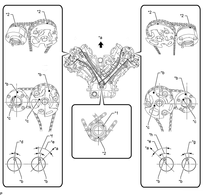
| *1 | Crankshaft Timing Gear Key | *2 | Timing Mark |
| *a | Toward Ceiling | *b | Timing Mark Position |
| *c | Knock Pin Position | *d | Approximately 2° |
| *e | Approximately 45° | *f | Approximately 16° |
| *g | Approximately 18° | *h | Approximately 32° |
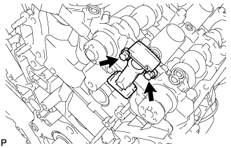
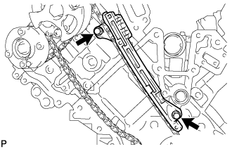
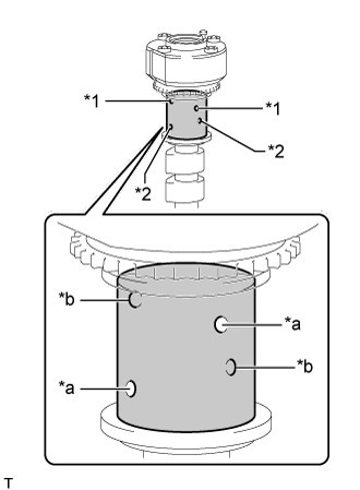
| 3. REMOVE NO. 1 CHAIN TENSIONER ASSEMBLY LH |

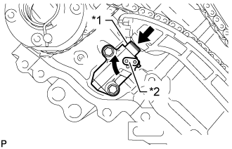
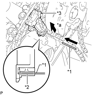
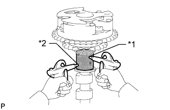
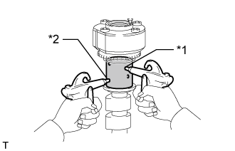
Move the stopper plate upward to release the lock and push the plunger deep into the No. 1 chain tensioner.
| *1 | Plunger |
| *2 | Stopper Plate |

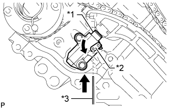
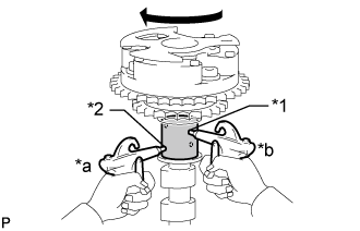
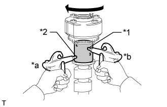
Move the stopper plate downward to set the lock and insert a hexagon wrench into the stopper plate hole.
| *1 | Plunger |
| *2 | Stopper Plate |
| *3 | Hexagon Wrench |

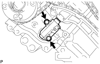
Remove the 2 bolts, No. 1 chain tensioner LH and gasket.
| 4. REMOVE CHAIN TENSIONER SLIPPER LH |
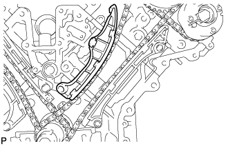
| 5. REMOVE NO. 1 CHAIN VIBRATION DAMPER LH |
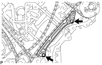
Remove the 2 bolts and No. 1 chain vibration damper LH.
| 6. REMOVE NO. 1 CHAIN SUB-ASSEMBLY LH |
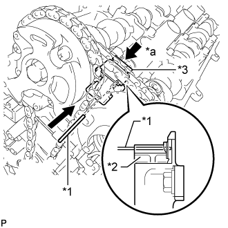
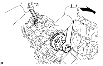
While pushing down the No. 3 chain tensioner, insert a pin with a diameter of 1.0 mm (0.0394 in.) into the hole to fix the tensioner in place.
| *1 | Pin |
| *2 | Plunger |
| *3 | No. 3 Chain Tensioner |
| *a | Push |

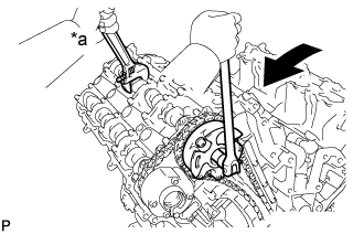
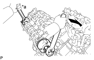
Hold the hexagonal portion of the camshaft with a wrench and loosen the bolt.
| *a | Hold |
 | Turn |
- NOTICE:

Hold the hexagonal portion of the camshaft with a wrench and loosen the bolt.
| *a | Hold |
| Turn |
- NOTICE:
Remove the 2 bolts. Then with the No. 1 and No. 2 chains still connected to the gears, remove the camshaft timing gear, camshaft timing exhaust gear and crankshaft timing sprocket LH.
Remove the No. 1 and No. 2 chains from the gears.
| 7. REMOVE NO. 3 CHAIN TENSIONER ASSEMBLY |
Remove the 2 bolts and No. 3 chain tensioner.
| 8. REMOVE NO. 1 CHAIN TENSIONER ASSEMBLY RH |
Move the stopper plate upward to release the lock and push the plunger deep into the No. 1 chain tensioner.
| *1 | Plunger |
| *2 | Stopper Plate |
Move the stopper plate downward to set the lock and insert a hexagon wrench into the stopper plate hole.
| *1 | Plunger |
| *2 | Stopper Plate |
| *3 | Hexagon Wrench |
Remove the 2 bolts and No. 1 chain tensioner RH.
| 9. REMOVE CHAIN TENSIONER SLIPPER RH |
| 10. REMOVE NO. 1 CHAIN VIBRATION DAMPER RH |
Remove the 2 bolts and No. 1 chain vibration damper RH.
| 11. REMOVE NO. 1 CHAIN SUB-ASSEMBLY RH |
While raising up the No. 2 chain tensioner, insert a pin with a diameter of 1.0 mm (0.0394 in.) into the hole to fix the tensioner in place.
| *1 | Pin |
| *2 | Plunger |
| *3 | No. 2 Chain Tensioner |
| *a | Push |
Hold the hexagonal portion of the camshaft with a wrench and loosen the bolt.
| *a | Hold |
| Turn |
- NOTICE:

Hold the hexagonal portion of the camshaft with a wrench and loosen the bolt.
| *a | Hold |
| Turn |
- NOTICE:
Remove the 2 bolts. Then with the No. 1 and No. 2 chains still connected to the gears, remove the camshaft timing gear, camshaft timing exhaust gear and crankshaft timing sprocket RH.
Remove the No. 1 and No. 2 chains from the gears.
| 12. REMOVE NO. 2 CHAIN TENSIONER ASSEMBLY |

Remove the 2 bolts and No. 2 chain tensioner.
| 13. REMOVE CAMSHAFT BEARING CAP LH |
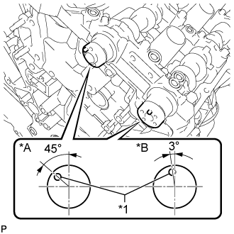
Make sure that the knock pins of the camshafts are positioned as shown in the illustration.
| *A | for Intake Side |
| *B | for Exhaust Side |
| *1 | Knock Pin |

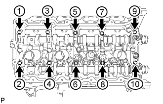
Uniformly loosen and remove the 10 bearing cap bolts in the sequence shown in the illustration.

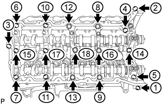
Uniformly loosen and remove the 18 bearing cap bolts in the sequence shown in the illustration.
- NOTICE:
- Uniformly loosen the bolts while keeping the camshaft level.
Remove the 6 camshaft bearing caps.
- HINT:
- Arrange the removed parts in the correct order.
| 14. REMOVE NO. 3 CAMSHAFT SUB-ASSEMBLY |
Remove the No. 3 camshaft from the camshaft housing LH.
| 15. REMOVE NO. 4 CAMSHAFT SUB-ASSEMBLY |
Remove the No. 4 camshaft from the camshaft housing LH.
| 16. REMOVE CAMSHAFT HOUSING SUB-ASSEMBLY LH |

Remove the camshaft housing by prying between the cylinder head and camshaft housing with a screwdriver.
| *1 | Protective Tape |
- NOTICE:
- Be careful not to damage the contact surfaces of the cylinder head and camshaft housing.
- HINT:
- Tape the screwdriver tip before use.
| 17. REMOVE CAMSHAFT BEARING CAP RH |
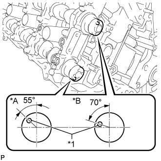
Make sure that the knock pins of the camshafts are positioned as shown in the illustration.
| *A | for Exhaust Side |
| *B | for Intake Side |
| *1 | Knock Pin |
Uniformly loosen and remove the 10 bearing cap bolts in the sequence shown in the illustration.
Uniformly loosen and remove the 18 bearing cap bolts in the sequence shown in the illustration.
- NOTICE:
- Uniformly loosen the bolts while keeping the camshaft level.
Remove the 6 camshaft bearing caps.
- HINT:
- Arrange the removed parts in the correct order.
| 18. REMOVE NO. 1 CAMSHAFT SUB-ASSEMBLY |
Remove the No. 1 camshaft from the camshaft housing RH.
| 19. REMOVE NO. 2 CAMSHAFT SUB-ASSEMBLY |
Remove the No. 2 camshaft from the camshaft housing RH.
| 20. REMOVE CAMSHAFT HOUSING SUB-ASSEMBLY RH |
Remove the camshaft housing by prying between the cylinder head and camshaft housing with a screwdriver.
| *1 | Protective Tape |
- NOTICE:
- Be careful not to damage the contact surfaces of the cylinder head and camshaft housing.
- HINT:
- Tape the screwdriver tip before use.
| 21. INSPECT CAMSHAFT TIMING GEAR ASSEMBLY |
Install the camshaft bearing cap ().
- HINT:
- Only install the intake camshaft.
Install the camshaft housing ().
- HINT:
- Do not use seal packing when installing the camshaft housing as the installation is temporary.
Apply a light coat of engine oil to the camshaft and camshaft timing gear.

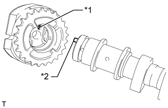
Using the hexagonal portion of the camshaft, align the knock pin of the camshaft with the pin hole of the camshaft timing gear and install the camshaft timing gear.
| *1 | Knock Pin |
| *2 | Pin Hole |
- NOTICE:

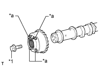
| *1 | Flange Bolt |
| *2 | Straight Pin |
| *a | Do not remove |
Apply a light coat of engine oil to the threads and under the head of the bolt.
Using a wrench to hold the hexagonal portion of the camshaft, install the camshaft timing gear flange bolt.
- Torque:
- 100 N*m{ 1020 kgf*cm, 74 ft.*lbf}
| *a | Hold |
| Turn |
Remove the camshaft bearing cap ().
Check the lock of the camshaft timing gear.
Clamp the camshaft in a vise and confirm that the camshaft timing gear is locked.
- NOTICE:
- Be careful not to damage the camshaft.

Release the lock pin.
| *1 | Advance Side Path |
| *2 | Retard Side Path |
| *a | Open |
| *b | Close |
 | Vinyl Tape |
Clean the cam journal with non-residue solvent.
Cover the 4 oil paths of the cam journal with vinyl tape as shown in the illustration.
Break through the tape over the advance side path. Then break through the tape over the retard side path on the opposite side of the advanced side path as shown in the illustration.
Apply compressed air at approximately 200 kPa (2.0 kgf/cm2, 29 psi) to the two paths accessible through the holes in the tape.
| *1 | Advance Side Path |
| *2 | Retard Side Path |
- NOTICE:
- Cover the paths with a piece of cloth when applying pressure to keep oil from splashing.
Check that the camshaft timing gear revolves in the advance direction when reducing the air pressure applied to the retard side path.
| *1 | Advance Side Path |
| *2 | Retard Side Path |
| *a | Decompress |
| *b | Hold Pressure |
- HINT:
- This operation releases the lock pin which holds the timing gear in the most retarded position.
When the camshaft timing gear reaches the most advanced position, release the air pressure from the retard side path and advance side path in that order.
- NOTICE:
- Do not release the air pressure from the advance side path first. The gear may abruptly shift in the retard direction and break the lock pin.
Check for smooth rotation.
Turn the camshaft timing gear within its movable range (21°) 2 or 3 times, but do not turn it to the most retarded position. Make sure that the gear turns smoothly.
- NOTICE:
- Do not use air pressure to perform the smooth rotation check.
Check the lock at the most retarded position.
Confirm that the camshaft timing gear becomes locked at the most retarded position.
Install the camshaft bearing cap ().
- HINT:
- Only install the intake camshaft.
Install the camshaft housing ().
- HINT:
- Do not use seal packing when installing the camshaft housing as the installation is temporary.
Hold the hexagonal portion of the camshaft with a wrench and loosen the flange bolt.
| *a | Hold |
| Turn |
Remove the camshaft bearing cap ().
Remove the flange bolt and camshaft timing gear.
| 22. INSPECT CAMSHAFT TIMING EXHAUST GEAR ASSEMBLY |
Install the camshaft bearing cap ().
- HINT:
- Only install the exhaust camshaft.
Install the camshaft housing ().
- HINT:
- Do not use seal packing when installing the camshaft housing as the installation is temporary.
Apply a light coat of engine oil to the camshaft and camshaft timing exhaust gear.
Using the hexagonal portion of the camshaft, align the knock pin of the camshaft with the pin hole of the camshaft timing exhaust gear and install the camshaft timing exhaust gear.
| *1 | Pin Hole |
| *2 | Knock Pin |
- NOTICE:
| *1 | Flange Bolt |
| *a | Do not remove |
Apply a light coat of engine oil to the threads and under the head of the bolt.
Using a wrench to hold the hexagonal portion of the camshaft, install the camshaft timing exhaust gear flange bolt.
- Torque:
- 100 N*m{ 1020 kgf*cm, 74 ft.*lbf}
| *a | Hold |
| Turn |
Remove the camshaft bearing cap ().
Check the camshaft timing exhaust gear lock.
Make sure that the camshaft timing exhaust gear is locked.
Release the lock pin.
| *1 | Advance Side Path |
| *2 | Retard Side Path |
| *a | Open |
| *b | Close |
| Vinyl Tape |
Cover the 4 oil paths of the cam journal with vinyl tape as shown in the illustration.
Break through the tape over the advance side path. Then break through the tape over the retard side path on the opposite side of the advanced side path as shown in the illustration.
Apply compressed air at approximately 200 kPa (2.0 kgf/cm2, 29 psi) to the two paths accessible through the holes in the tape (the advance side path and retard side path).
| *1 | Advance Side Path |
| *2 | Retard Side Path |
- NOTICE:
- Cover the paths with a piece of cloth when applying pressure to keep oil from splashing.
Check that the camshaft timing exhaust gear turns in the retard direction when reducing the air pressure applied to the advance side path.
| *1 | Advance Side Path |
| *2 | Retard Side Path |
| *a | Hold Pressure |
| *b | Decompress |
- HINT:
- The lock pin is released and the camshaft timing exhaust gear turns in the retard direction.
When the camshaft timing exhaust gear moves to the most retarded position, release the air pressure from the advance side path, and then release the air pressure from the retard side path.
- NOTICE:
- Be sure to release the air pressure from the advance side path first. If the air pressure of the retard side path is released first, the camshaft timing exhaust gear may abruptly shift in the advance direction and break the lock pin or other parts.
Check for smooth rotation.
Turn the camshaft timing exhaust gear within its movable range (18.5°) 2 or 3 times, but do not turn it to the most advanced position. Make sure that the gear turns smoothly.
- NOTICE:
- When the air pressure is released from the advance side path and then from the retard side path, the gear automatically returns to the most advanced position, due to the advance assist spring operation, and locks. Gradually release the air pressure from the retard side path before performing the smooth rotation check.
Check the lock at the most advanced position.
Make sure that the camshaft timing exhaust gear becomes locked at the most advanced position.
Install the camshaft bearing cap ().
- HINT:
- Only install the exhaust camshaft.
Install the camshaft housing ().
- HINT:
- Do not use seal packing when installing the camshaft housing as the installation is temporary.

Hold the hexagonal portion of the camshaft with a wrench and loosen the flange bolt.
| *a | Hold |
| Turn |
Remove the camshaft bearing cap ().
Remove the flange bolt and camshaft timing exhaust gear.