Land Cruiser URJ200 URJ202 GRJ200 VDJ200 - 1GR-FE ENGINE MECHANICAL
CYLINDER BLOCK - DISASSEMBLY
| 1. INSPECT CONNECTING ROD THRUST CLEARANCE |

Using a dial indicator, measure the thrust clearance while moving the connecting rod back and forth.
- Standard thrust clearance:
- 0.15 to 0.30 mm (0.00591 to 0.0118 in.)
- Maximum thrust clearance:
- 0.35 mm (0.0138 in.)
If the thrust clearance is more than the maximum, replace one or more connecting rods as necessary.
- Standard connecting rod thickness:
- 20.80 to 20.85 mm (0.819 to 0.821 in.)
If necessary, replace the crankshaft.
| 2. INSPECT CONNECTING ROD OIL CLEARANCE |
Check the matchmarks on the connecting rod and cap to ensure correct reassembly.
Remove the 2 connecting rod cap bolts.

Using the 2 removed connecting rod cap bolts, remove the connecting rod cap and lower bearing by wiggling the connecting rod cap right and left.
- HINT:
- Keep the lower bearing and connecting rod cap together.
Clean the crank pin and bearing.
Check the crank pin and bearing for pitting and scratches. If the crank pin or bearing is damaged, replace the bearings. If necessary, replace the crankshaft.
Lay a strip of Plastigage across the crank pin.
| *1 | Plastigage |
Install the connecting rod cap ().
- NOTICE:
- Do not turn the crankshaft.
Remove the 2 bolts, connecting rod cap and lower bearing.
Measure the Plastigage at its widest point.
- Standard oil clearance:
- 0.040 to 0.066 mm (0.00157 to 0.00260 in.)
- Maximum oil clearance:
- 0.086 mm (0.00339 in.)
| *1 | Plastigage |
If the oil clearance is more than the maximum, replace the bearings. If necessary, inspect the crankshaft.
- HINT:

- If replacing a bearing, replace it with one that has the same number as the number marked on the connecting rod. There are 4 sizes of standard bearings, marked "1", "2", "3" and "4" accordingly.
- Standard Connecting Rod Diameter:
Item Specified Condition Mark 1 59.000 to 59.006 mm (2.32283 to 2.32307 in.) Mark 2 59.007 to 59.012 mm (2.32311 to 2.32330 in.) Mark 3 59.013 to 59.018 mm (2.32334 to 2.32354 in.) Mark 4 59.019 to 59.024 mm (2.32358 to 2.32377 in.)
- Standard Bearing Center Wall Thickness:
Item Specified Condition Mark 1 1.484 to 1.487 mm (0.05843 to 0.05854 in.) Mark 2 1.487 to 1.490 mm (0.05854 to 0.05866 in.) Mark 3 1.490 to 1.493 mm (0.05866 to 0.05878 in.) Mark 4 1.493 to 1.496 mm (0.05878 to 0.05900 in.)
- Standard crankshaft pin diameter:
- 55.992 to 56.000 mm (2.2044 to 2.2047 in.)
| *1 | Number Mark |
Completely remove the Plastigage.
Perform the inspection above for each crank pin.
| 3. REMOVE PISTON SUB-ASSEMBLY WITH CONNECTING ROD |

Using a ridge reamer, remove all the carbon from the top of the cylinder.
Push out the piston with connecting rod and upper bearing through the top of the cylinder block.
- HINT:
| 4. REMOVE CONNECTING ROD BEARING |
Remove the connecting rod bearings from the connecting rods and connecting rod caps.
- HINT:
- Arrange the removed parts in the correct order.
| 5. REMOVE PISTON RING SET |

Using a piston ring expander, remove the 2 compression rings.
Remove the 2 side rails and oil ring (expander) by hand.
| 6. REMOVE PISTON WITH PIN SUB-ASSEMBLY |
Disconnect the connecting rod from the piston.

Using a screwdriver, pry out the 2 snap rings.
Gradually heat the piston to approximately 80°C (176°F).

Using a plastic-faced hammer and brass bar, lightly tap out the piston pin and remove the connecting rod.
- HINT:
| 7. INSPECT CRANKSHAFT THRUST CLEARANCE |
Using a dial indicator, measure the thrust clearance while prying the crankshaft back and forth with a screwdriver.
- Standard thrust clearance:
- 0.04 to 0.24 mm (0.00157 to 0.00945 in.)
- Maximum thrust clearance:
- 0.30 mm (0.0118 in.)
If the thrust clearance is more than the maximum, replace the thrust washers as a set.
- Standard thrust washer thickness:
- 1.93 to 1.98 mm (0.0760 to 0.0780 in.)
If necessary, replace the crankshaft.
| 8. INSPECT CRANKSHAFT OIL CLEARANCE |
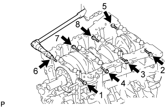
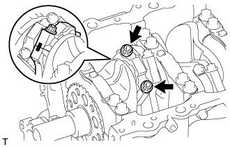
Uniformly loosen and remove the 8 bearing cap bolts and 8 seal washers in several steps in the sequence shown in the illustration.

Uniformly loosen and remove the 16 bearing cap bolts in several steps in the sequence shown in the illustration.
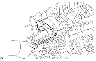
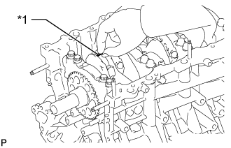
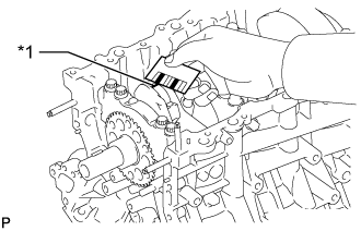
Using a screwdriver, pry out the bearing caps. Remove the 4 bearing caps and lower bearings.
- NOTICE:
Remove the 2 lower crankshaft thrust washers.
- HINT:
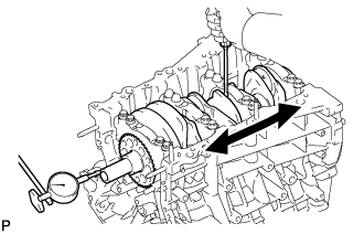
Lift out the crankshaft.

Remove the 2 upper thrust washers.
- HINT:
Clean each crankshaft journal and bearing.
Check each crankshaft journal and bearing for pitting and scratches.
If the journal or bearing is damaged, replace the bearings. If necessary, replace the crankshaft.
Place the crankshaft on the cylinder block.

Lay a strip of Plastigage across each journal.
| *1 | Plastigage |
Install the crankshaft bearing cap ().
- NOTICE:
- Do not turn the crankshaft.
Remove the crankshaft bearing cap.

Measure the Plastigage at its widest point.
- Standard oil clearance:
- 0.026 to 0.046 mm (0.00102 to 0.00181 in.)
- Maximum clearance:
- 0.080 mm (0.00315 in.)
If the oil clearance is more than the maximum, replace the bearings. If necessary, replace the crankshaft.
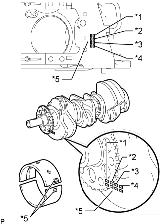
If replacing a bearing, replace it with one that has the same number. If the number of the bearing cannot be determined, select the correct bearing by adding together the numbers imprinted on the cylinder block and crankshaft, and then refer to the table below for the appropriate bearing number. There are 5 sizes of standard bearings, marked "1", "2", "3", "4" and "5" accordingly.
- New Bearing:
Item Specified Condition Cylinder block main journal bore diameter (A)
+
Crankshaft main journal diameter (B)0 to 5 6 to 11 12 to 17 18 to 23 24 to 28 Use bearing 1 2 3 4 5
| *1 | No. 1 |
| *2 | No. 2 |
| *3 | No. 3 |
| *4 | No. 4 |
| *5 | Number Mark |
EXAMPLE:
Cylinder block "11" (A) + Crankshaft "06" (B) = Total number 17 (Use bearing "3")
- Standard Cylinder Block Main Journal Bore Diameter (A):
Mark Specified Condition Mark 00 77.000 mm (3.03149 in.) Mark 01 77.001 mm (3.03152 in.) Mark 02 77.002 mm (3.03156 in.) Mark 03 77.003 mm (3.03160 in.) Mark 04 77.004 mm (3.03164 in.) Mark 05 77.005 mm (3.03168 in.) Mark 06 77.006 mm (3.03172 in.) Mark 07 77.007 mm (3.03176 in.) Mark 08 77.008 mm (3.03180 in.) Mark 09 77.009 mm (3.03184 in.) Mark 10 77.010 mm (3.03188 in.) Mark 11 77.011 mm (3.03192 in.) Mark 12 77.012 mm (3.03196 in.) Mark 13 77.013 mm (3.03200 in.) Mark 14 77.014 mm (3.03204 in.) Mark 15 77.015 mm (3.03208 in.) Mark 16 77.016 mm (3.03211 in.)
- Standard Crankshaft Main Journal Diameter (B):
Item Specified Condition Mark 00 71.999 to 72.000 mm (2.83460 to 2.83464 in.) Mark 01 71.998 to 71.999 mm (2.83456 to 2.83460 in.) Mark 02 71.997 to 71.998 mm (2.83452 to 2.83456 in.) Mark 03 71.996 to 71.997 mm (2.83448 to 2.83452 in.) Mark 04 71.995 to 71.996 mm (2.83440 to 2.83448 in.) Mark 05 71.994 to 71.995 mm (2.83440 to 2.83444 in.) Mark 06 71.993 to 71.994 mm (2.83436 to 2.83440 in.) Mark 07 71.992 to 71.993 mm (2.83432 to 2.83436 in.) Mark 08 71.991 to 71.992 mm (2.83428 to 2.83432 in.) Mark 09 71.990 to 71.991 mm (2.83424 to 2.83428 in.) Mark 10 71.989 to 71.990 mm (2.83420 to 2.83424 in.) Mark 11 71.988 to 71.989 mm (2.83416 to 2.83420 in.)
- Standard Bearing Center Wall Thickness:
Item Specified Condition Mark 1 2.488 to 2.491 mm (0.0980 to 0.0981 in.) Mark 2 2.491 to 2.494 mm (0.0981 to 0.0982 in.) Mark 3 2.494 to 2.497 mm (0.0982 to 0.0983 in.) Mark 4 2.497 to 2.500 mm (0.0983 to 0.0984 in.) Mark 5 2.500 to 2.503 mm (0.0984 to 0.0985 in.)
Completely remove the Plastigage.
Perform the inspection above for each journal.
| 9. REMOVE CRANKSHAFT |
Lift out the crankshaft.
Remove the 2 upper thrust washers.
| 10. REMOVE CRANKSHAFT BEARING |
Remove the crankshaft bearings from the bearing caps and cylinder block.
- HINT:
- Arrange the removed parts in the correct order.
| 11. REMOVE NO. 1 OIL NOZZLE SUB-ASSEMBLY |

Using a 5 mm hexagon socket wrench, remove the 3 bolts and 3 oil nozzles.
| 12. REMOVE STUD BOLT |
- NOTICE:
- If a stud bolt is deformed or its threads are damaged, replace it.