REMOVE FRONT DOOR SCUFF PLATE LH (for Double Swing Out Type Back Door)
REMOVE FRONT DOOR SCUFF PLATE RH (except Double Swing Out Type Back Door)
REMOVE NO. 2 INSTRUMENT PANEL FINISH PANEL CUSHION (for Double Swing Out Type Back Door)
REMOVE NO. 1 INSTRUMENT PANEL FINISH CUSHION (except Double Swing Out Type Back Door)
REMOVE LOWER INSTRUMENT PANEL PAD SUB-ASSEMBLY LH (for Double Swing Out Type Back Door)
REMOVE LOWER INSTRUMENT PANEL PAD SUB-ASSEMBLY RH (except Double Swing Out Type Back Door)
Knee Airbag Assembly (For Front Passenger Side) -- Removal |
- HINT:
- Use the same procedure for RHD and LHD vehicles.
- The procedure listed below is for LHD vehicles.
| 1. PRECAUTION |
- CAUTION:
- Be sure to read Precaution thoroughly before servicing (Click here).
- NOTICE:
- After turning the ignition switch off, waiting time may be required before disconnecting the cable from the negative (-) battery terminal. Therefore, make sure to read the disconnecting the cable from the negative (-) battery terminal notices before proceeding with work (Click here).
| 2. DISCONNECT CABLE FROM NEGATIVE BATTERY TERMINAL |
- CAUTION:
- Wait at least 90 seconds after disconnecting the cable from the negative (-) battery terminal to disable the SRS system.
- NOTICE:
- When disconnecting the cable, some systems need to be initialized after the cable is reconnected (Click here).
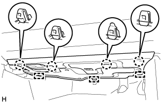
| 3. REMOVE FRONT DOOR SCUFF PLATE LH (for Double Swing Out Type Back Door) |
 |
Detach the 7 claws and 4 clips, and remove the front door scuff plate LH.
| 4. REMOVE FRONT DOOR SCUFF PLATE RH (except Double Swing Out Type Back Door) |
- HINT:
- Use the same procedures described for the LH side.
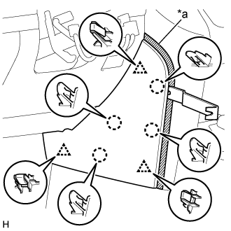
| 5. REMOVE NO. 2 INSTRUMENT PANEL FINISH PANEL CUSHION (for Double Swing Out Type Back Door) |
for Type A:
Put protective tape around the No. 2 instrument panel finish panel cushion.
Text in Illustration *a Protective Tape Using a moulding remover B, detach the 4 claws and 3 clips and remove the No. 2 instrument panel finish panel cushion.
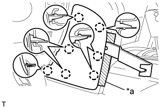
for Type B:
Put protective tape around the No. 2 instrument panel finish panel cushion.
Text in Illustration *a Protective Tape Using a moulding remover, detach the 7 claws and remove the No. 2 instrument panel finish panel cushion.
| 6. REMOVE NO. 1 INSTRUMENT PANEL FINISH CUSHION (except Double Swing Out Type Back Door) |
for Type A:
Put protective tape around the No. 1 instrument panel finish panel cushion.
Text in Illustration *a Protective Tape Using a moulding remover B, detach the 4 claws and 3 clips and remove the No. 2 instrument panel finish panel cushion.
for Type B:
Put protective tape around the No. 1 instrument panel finish panel cushion.
Text in Illustration *a Protective Tape Using a moulding remover, detach the 7 claws and remove the No. 2 instrument panel finish panel cushion.
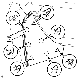
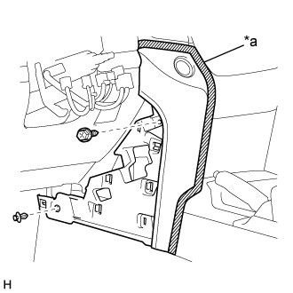
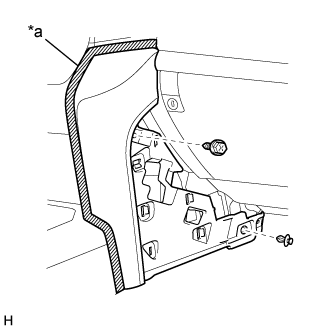
| 7. REMOVE LOWER INSTRUMENT PANEL PAD SUB-ASSEMBLY LH (for Double Swing Out Type Back Door) |
for Type A:
Put protective tape around the lower instrument panel pad sub-assembly LH.
Text in Illustration *a Protective Tape Remove the clip and screw.
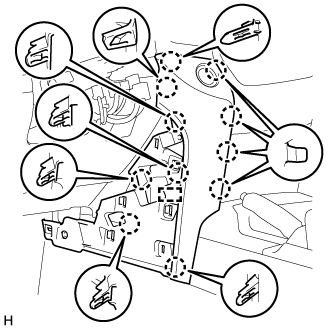
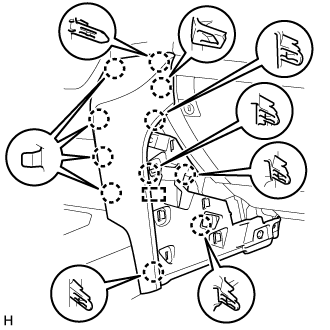
Detach the 11 claws and guide.
Disconnect the connector and detach the clamps and remove the lower instrument panel pad sub-assembly LH.
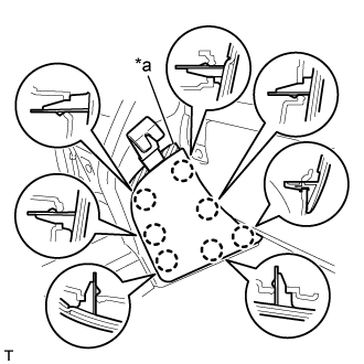
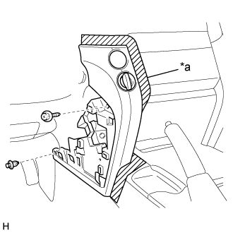
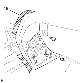
for Type B:
Put protective tape around the lower instrument panel pad sub-assembly LH.
Text in Illustration *a Protective Tape Remove the clip and screw.
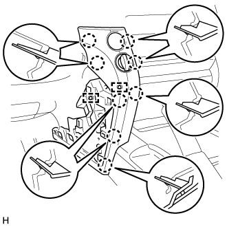
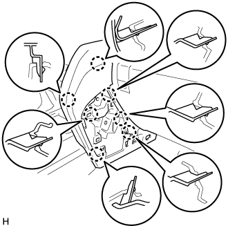
Detach the 8 claws and 2 guides and remove the lower instrument panel pad sub-assembly LH.
| 8. REMOVE LOWER INSTRUMENT PANEL PAD SUB-ASSEMBLY RH (except Double Swing Out Type Back Door) |
for Type A:
Put protective tape around the lower instrument panel pad sub-assembly RH.
Text in Illustration *a Protective Tape Remove the clip and screw.
Detach the 11 claws and guide and remove the lower instrument panel pad sub-assembly RH.
for Type B:
Put protective tape around the lower instrument panel pad sub-assembly RH.
Text in Illustration *a Protective Tape Remove the clip and screw.
Detach the 7 claws and remove the lower instrument panel pad sub-assembly RH.
| 9. REMOVE NO. 2 INSTRUMENT PANEL UNDER COVER SUB-ASSEMBLY |
 |
Detach the 4 claws and 3 guides.
Disconnect the connector and remove the No. 2 instrument panel under cover sub-assembly.
| 10. REMOVE FRONT PASSENGER SIDE KNEE AIRBAG ASSEMBLY |
Remove the 4 bolts.
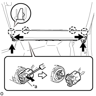 |
Detach the 4 claws and remove the front passenger side knee airbag assembly.
Using a screwdriver, release the connector lock and disconnect the airbag connector.
Text in Illustration *a Connector Lock 
Protective Tape - NOTICE:
- When handling the airbag connector, take care not to damage the airbag wire harness.
- CAUTION:
- Tape the screwdriver tip before use.