Dtc B150A Lost Communication With Hmi-Lan
DESCRIPTION
WIRING DIAGRAM
INSPECTION PROCEDURE
CHECK FOR DTC (NAVIGATION SYSTEM*1 or AUDIO AND VISUAL SYSTEM*2)
CHECK HARNESS AND CONNECTOR (COMBINATION METER ASSEMBLY - NAVIGATION RECEIVER ASSEMBLY)
CHECK COMBINATION METER ASSEMBLY
CHECK HARNESS AND CONNECTOR (COMBINATION METER ASSEMBLY - RADIO AND DISPLAY RECEIVER ASSEMBLY)
CHECK COMBINATION METER ASSEMBLY
DTC B150A Lost Communication with HMI-LAN |
DESCRIPTION
- *1: w/ Navigation System
- *2: w/ Audio and Display System
The combination meter assembly receives a text data signal from the multi-media module receiver assembly*1 or radio and display receiver assembly*2 via local bus communication.Based on this signal, audio and visual system or navigation system information is displayed on the multi-information display.This DTC is stored when the combination meter assembly cannot receive the signal.DTC No.
| DTC Detection Condition
| Trouble Area
|
B150A
| After the combination meter assembly receives a registration information signal, which is sent by the multi-media module receiver assembly when the ignition switch is turned ACC, 1 or more times, the combination meter assembly does not receive the signal for 30 seconds or more.
| - Harness or connector
- Multi-media module receiver assembly*1
- Radio and display receiver assembly*2
- Combination meter assembly
|
WIRING DIAGRAM
| for LHD with Navigation System: |
| for RHD with Navigation System: |
| w/ Audio and Display System: |
INSPECTION PROCEDURE
| 1.CHECK FOR DTC (NAVIGATION SYSTEM*1 or AUDIO AND VISUAL SYSTEM*2) |
- *1: w/ Navigation System
- *2: w/ Audio and Display System
Check if navigation system DTCs are output (Click here).*1
Check if audio and visual system DTCs are output (Click here).*2
- Result:
Result
| Proceed to
|
Navigation system DTCs are not output. (w/ Navigation System)
| A
|
Audio and visual system DTCs are not output. (w/ Audio and Display System)
| B
|
Navigation system DTCs are output. (w/ Navigation System)
| C
|
Audio and visual system DTCs are output. (w/ Audio and Display System)
| D
|
| 2.CHECK HARNESS AND CONNECTOR (COMBINATION METER ASSEMBLY - NAVIGATION RECEIVER ASSEMBLY) |
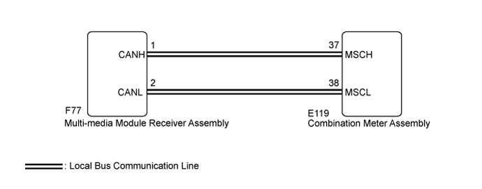
Disconnect the E119 combination meter assembly connector.
Disconnect the F77 multi-media module receiver assembly connector.
Measure the resistance according to the value(s) in the table below.
- Standard Resistance (for LHD):
Tester Connection
| Condition
| Specified Condition
|
E119-37 (MSCH) - F77-1 (CANH)
| Always
| Below 1 Ω
|
E119-38 (MSCL) - F77-2 (CANL)
| Always
| Below 1 Ω
|
E119-37 (MSCH) or F77-1 (CANH) - Body ground
| Always
| 10 kΩ or higher
|
E119-38 (MSCL) or F77-2 (CANL) - Body ground
| Always
| 10 kΩ or higher
|
- Standard Resistance (for RHD):
Tester Connection
| Condition
| Specified Condition
|
E119-37 (MSCH) - F77-20 (CAH2)
| Always
| Below 1 Ω
|
E119-38 (MSCL) - F77-21 (CAL2)
| Always
| Below 1 Ω
|
E119-37 (MSCH) or F77-20 (CAH2) - Body ground
| Always
| 10 kΩ or higher
|
E119-38 (MSCL) or F77-21 (CAL2) - Body ground
| Always
| 10 kΩ or higher
|
| | REPAIR OR REPLACE HARNESS OR CONNECTOR |
|
|
| 3.CHECK COMBINATION METER ASSEMBLY |
Replace the combination meter assembly with a new or known good one (Click here).
Turn the ignition switch to ON and wait 30 seconds.
- NOTICE:
- A maximum of 30 seconds is required to send/receive the registration information between the combination meter assembly and navigation receiver assembly.
Operate the steering pad switch assembly and check that the audio tab illuminates.
Check for DTCs (Click here).
- Result:
Result
| Proceed to
|
The audio tab illuminates and DTC B150A is not output.
| A
|
The audio tab does not illuminate and DTC B150A is output.
| B
|
| OK |
|
|
|
| END (COMBINATION METER ASSEMBLY IS DEFECTIVE) |
|
| 4.CHECK HARNESS AND CONNECTOR (COMBINATION METER ASSEMBLY - RADIO AND DISPLAY RECEIVER ASSEMBLY) |
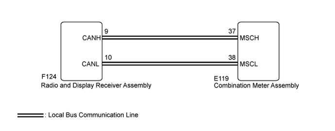
Disconnect the E119 combination meter assembly connector.
Disconnect the F124 radio and display receiver assembly connector.
Measure the resistance according to the value(s) in the table below.
- Standard Resistance:
Tester Connection
| Condition
| Specified Condition
|
E119-37 (MSCH) - F124-9 (CANH)
| Always
| Below 1 Ω
|
E119-38 (MSCL) - F124-10 (CANL)
| Always
| Below 1 Ω
|
E119-37 (MSCH) or F124-9 (CANH) - Body ground
| Always
| 10 kΩ or higher
|
E119-38 (MSCL) or F124-10 (CANL) - Body ground
| Always
| 10 kΩ or higher
|
| | REPAIR OR REPLACE HARNESS OR CONNECTOR |
|
|
| 5.CHECK COMBINATION METER ASSEMBLY |
Replace the combination meter assembly with a new or known good one (Click here).
Turn the ignition switch to ON and wait 30 seconds.
- NOTICE:
- A maximum of 30 seconds is required to send/receive the registration information between the combination meter assembly and the radio and display receiver assembly.
Operate the steering pad switch assembly and check that the audio tab illuminates.
Check for DTCs (Click here).
- Result:
Result
| Proceed to
|
The audio tab illuminates and DTC B150A is not output.
| A
|
The audio tab does not illuminate and DTC B150A is output.
| B
|
| | REPLACE RADIO AND DISPLAY RECEIVER ASSEMBLY (Click here) |
|
|
| OK |
|
|
|
| END (COMBINATION METER ASSEMBLY IS DEFECTIVE) |
|