INSTALL LOWER NO. 2 INSTRUMENT PANEL AIRBAG ASSEMBLY (w/ Passenger Side Knee Airbag)
INSTALL LOWER INSTRUMENT PANEL (w/o Passenger Side Knee Airbag)
INSTALL NO. 2 INSTRUMENT PANEL UNDER COVER SUB-ASSEMBLY (w/ Floor Under Cover)
Glove Box Light -- Installation |
- HINT:
- Use the same procedures for the RHD and LHD.
- The procedures listed below are the LHD side.
| 1. INSTALL GLOVE BOX LIGHT ASSEMBLY |
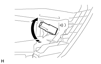 |
Install the glove box light assembly and twist it in the direction indicated by the arrow.
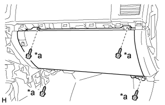
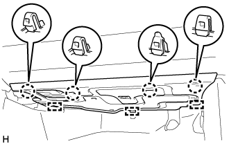
| 2. INSTALL LOWER NO. 2 INSTRUMENT PANEL FINISH PANEL |
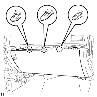 |
Connect the connector.
Attach the 3 claws to install the lower No. 2 instrument panel finish panel.
Install the 4 screws <C>.
Text in Illustration *a Screw <C>
 |
| 3. INSTALL INSTRUMENT PANEL BOX DOOR KNOB |
- HINT:
- Use the same procedure for both instrument panel box door knobs.
Attach the 2 claws to install the instrument panel box door knob.
 |
| 4. INSTALL NO. 3 INSTRUMENT CLUSTER FINISH PANEL GARNISH |
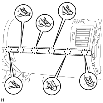 |
Attach the 6 claws to install the No. 3 instrument cluster finish panel garnish.
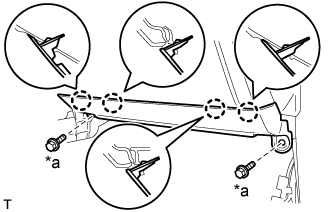
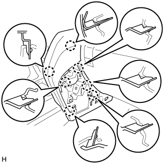
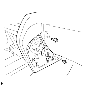
| 5. INSTALL LOWER NO. 2 INSTRUMENT PANEL AIRBAG ASSEMBLY (w/ Passenger Side Knee Airbag) |
Check that the ignition switch is off.
Check that the cable is disconnected from the negative (-) battery terminal.
- CAUTION:
- Wait at least 90 seconds after disconnecting the cable from the negative (-) battery terminal to disable the SRS system.
Connect the airbag connector and lock the connector lock.
Text in Illustration *a Connector Lock - NOTICE:
- When handling the airbag connector, take care not to damage the airbag wire harness.
 |
Attach the 4 claws to install the front passenger side knee airbag assembly.
Install the 4 bolts.
- Torque:
- 12 N*m{122 kgf*cm, 9 ft.*lbf}
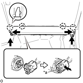
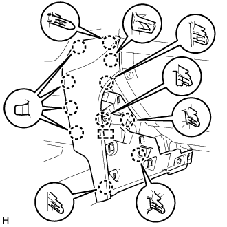
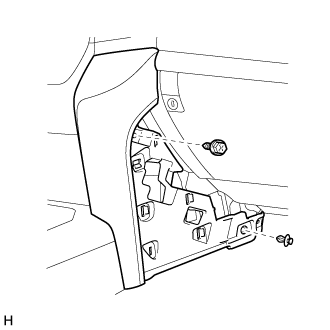
| 6. INSTALL LOWER INSTRUMENT PANEL (w/o Passenger Side Knee Airbag) |
 |
Attach the 4 claws to install the lower instrument panel.
Install the 2 bolts <B>.
Text in Illustration *a Bolt <B>
| 7. INSTALL NO. 2 INSTRUMENT PANEL UNDER COVER SUB-ASSEMBLY (w/ Floor Under Cover) |
 |
Connect the connector.
Attach the 3 guides.
Attach the 4 claws to install the No. 2 instrument panel under cover sub-assembly.
| 8. INSTALL FRONT DOOR SCUFF PLATE RH |
- HINT:
- Use the same procedures described for the LH side.
| 9. INSTALL INSTALL LOWER INSTRUMENT PANEL PAD SUB-ASSEMBLY RH |
for Type A:
Attach the 11 claws and guide to install the lower instrument panel pad sub-assembly RH.
Install the screw and clip.
for Type B:
Attach the 7 claws to install the lower instrument panel pad sub-assembly RH.
Install the screw and clip.
| 10. INSTALL NO. 1 INSTRUMENT PANEL FINISH CUSHION |
for Type A:
Attach the 4 claws and 3 clips to install the No. 1 instrument panel finish panel cushion.

for Type B:
Attach the 7 claws to install the panel No. 1 instrument panel finish panel cushion.
