Theft Deterrent System (W/O Entry And Start System) Security Horn Circuit
DESCRIPTION
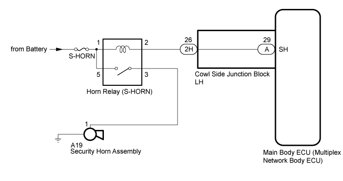
WIRING DIAGRAM
INSPECTION PROCEDURE
PERFORM ACTIVE TEST USING GTS (SECURITY HORN)
INSPECT SECURITY HORN ASSEMBLY
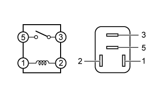
INSPECT HORN RELAY (S-HORN)
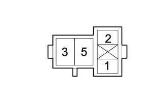
CHECK HARNESS AND CONNECTOR (HORN RELAY [S-HORN] - MAIN BODY ECU [MULTIPLEX NETWORK BODY ECU])
CHECK HARNESS AND CONNECTOR (BATTERY - HORN RELAY [S-HORN])
CHECK HARNESS AND CONNECTOR (HORN RELAY [S-HORN] - SECURITY HORN ASSEMBLY AND BODY GROUND)
CHECK HARNESS AND CONNECTOR (HORN RELAY [S-HORN] - COWL SIDE JUNCTION BLOCK LH)
THEFT DETERRENT SYSTEM (w/o Entry and Start System) - Security Horn Circuit |
DESCRIPTION
When the theft deterrent system is switched from the armed state to the alarm sounding state, the main body ECU (multiplex network body ECU) transmits a signal to cause the security horn to sound at intervals of 0.4 seconds.
WIRING DIAGRAM
INSPECTION PROCEDURE
- NOTICE:
- If the main body ECU (multiplex network body ECU) is replaced, refer to the Service Bulletin.
- Inspect the fuses for circuits related to this system before performing the following inspection procedure.
- *: w/ Door Control Battery
As the door control battery is installed between the vehicle battery and main body ECU (multiplex network body ECU), first perform the inspections in On-Vehicle Inspection to confirm that there are no malfunctions in the power source circuit for the main body ECU (multiplex network body ECU) before performing this troubleshooting procedure (Click here).
| 1.PERFORM ACTIVE TEST USING GTS (SECURITY HORN) |
Connect the GTS to the DLC3.
Turn the ignition switch ON.
Turn the GTS on.
Enter the following menus: Body Electrical / Main Body / Active Test.
According to the display on the GTS, perform the Active Test.
Main BodyTester Display
| Test Part
| Control Range
| Diagnostic Note
|
Security Horn
| Security horn
| OFF/ON
| -
|
- OK:
- The security horn assembly sounds and stops correctly when operated through the GTS.
ResultResult
| Proceed to
|
OK (for LHD)
| A
|
OK (for RHD)
| B
|
NG
| C
|
| | REPLACE MAIN BODY ECU (MULTIPLEX NETWORK BODY ECU) (Click here) |
|
|
| |
|
| A |
|
|
|
| REPLACE MAIN BODY ECU (MULTIPLEX NETWORK BODY ECU) (Click here) |
|
| 2.INSPECT SECURITY HORN ASSEMBLY |
Remove the security horn assembly (Click here).
Inspect the security horn assembly (Click here).
| 3.INSPECT HORN RELAY (S-HORN) |
Remove the horn relay (S-HORN).
Measure the resistance according to the value(s) in the table below.
- Standard Resistance:
Tester Connection
| Condition
| Specified Condition
|
3-5
| When battery voltage is applied between terminals 2-1
| Below 1 Ω
|
3-5
| When battery voltage is not applied between terminals 2-1
| 10 kΩ or higher
|
| | REPLACE HORN RELAY [S-HORN] |
|
|
| 4.CHECK HARNESS AND CONNECTOR (HORN RELAY [S-HORN] - MAIN BODY ECU [MULTIPLEX NETWORK BODY ECU]) |
Remove the main body ECU (multiplex network body ECU) from the cowl side junction block LH.
- for LHD: Click here
- for RHD: Click here
Connect the cowl side junction block LH connectors.
Remove the horn relay (S-HORN).
Measure the resistance according to the value(s) in the table below.
- Standard Resistance:
Tester Connection
| Condition
| Specified Condition
|
2 - A-29 (SH)
| Always
| Below 1 Ω
|
2 - Body ground
| Always
| 10 kΩ or higher
|
A-29 (SH) - Body ground
| Always
| 10 kΩ or higher
|
| 5.CHECK HARNESS AND CONNECTOR (BATTERY - HORN RELAY [S-HORN]) |
Remove the horn relay (S-HORN).
Measure the voltage according to the value(s) in the table below.
- Standard Voltage:
Tester Connection
| Condition
| Specified Condition
|
1 - Body ground
| Always
| 11 to 14 V
|
5 - Body ground
| Always
| 11 to 14 V
|
| | REPAIR OR REPLACE HARNESS OR CONNECTOR |
|
|
| 6.CHECK HARNESS AND CONNECTOR (HORN RELAY [S-HORN] - SECURITY HORN ASSEMBLY AND BODY GROUND) |
Remove the horn relay (S-HORN).
Disconnect the A53 security horn assembly connector.
Measure the resistance according to the value(s) in the table below.
- Standard Resistance:
Tester Connection
| Condition
| Specified Condition
|
3 - A53-1
| Always
| Below 1 Ω
|
3 - Body ground
| Always
| 10 kΩ or higher
|
A53-1 - Body ground
| Always
| 10 kΩ or higher
|
ResultResult
| Proceed to
|
OK (for LHD)
| A
|
OK (for RHD)
| B
|
NG
| C
|
| | REPLACE MAIN BODY ECU (MULTIPLEX NETWORK BODY ECU) (Click here) |
|
|
| | REPAIR OR REPLACE HARNESS OR CONNECTOR |
|
|
| A |
|
|
|
| REPLACE MAIN BODY ECU (MULTIPLEX NETWORK BODY ECU) (Click here) |
|
| 7.CHECK HARNESS AND CONNECTOR (HORN RELAY [S-HORN] - COWL SIDE JUNCTION BLOCK LH) |
Disconnect the 2H cowl side junction block LH connector.
Remove the horn relay (S-HORN).
Measure the resistance according to the value(s) in the table below.
- Standard Resistance:
Tester Connection
| Condition
| Specified Condition
|
2 - 2H-26
| Always
| Below 1 Ω
|
2 - Body ground
| Always
| 10 kΩ or higher
|
2H-26 - Body ground
| Always
| 10 kΩ or higher
|
ResultResult
| Proceed to
|
OK (for LHD)
| A
|
OK (for RHD)
| B
|
NG
| C
|
| |
|
| | REPAIR OR REPLACE HARNESS OR CONNECTOR |
|
|