Engine Immobiliser System (W/O Entry And Start System) Engine Does Not Start But Initial Combustion Occurs
DESCRIPTION
WIRING DIAGRAM
INSPECTION PROCEDURE
CLEAR DTC
CHECK FOR DTC
READ VALUE USING GTS (IMMOBILISER FUEL CUT)
CHECK WHETHER ENGINE STARTS
REGISTER ECU COMMUNICATION ID
CHECK WHETHER ENGINE STARTS
REPLACE ECM
CHECK WHETHER ENGINE STARTS
CHECK HARNESS AND CONNECTOR (TRANSPONDER KEY ECU ASSEMBLY - ECM)
CHECK TRANSPONDER KEY ECU ASSEMBLY
ENGINE IMMOBILISER SYSTEM (w/o Entry and Start System) - Engine does not Start but Initial Combustion Occurs |
DESCRIPTION
If the key ID codes of the key and transponder key ECU assembly match, the immobiliser system is unset and the engine start permission signal is sent to the ECM. When the ID codes of the transponder key ECU assembly and ECM match, the engine starts.
WIRING DIAGRAM
INSPECTION PROCEDURE
- NOTICE:
- If the transponder key ECU assembly or ECM is replaced, refer to Service Bulletin.
- When using the GTS with the vehicle ignition switch off, connect the GTS to the vehicle and turn a courtesy light switch on and off at intervals of 1.5 seconds or less until communication between the GTS and the vehicle begins. Then select the Model Code "KEY REGIST" under manual mode and enter the following menus: Body Electrical / Immobiliser. While using the GTS, periodically turn a courtesy light switch on and off at intervals of 1.5 seconds or less to maintain communication between the GTS and the vehicle.
Clear the DTCs (Click here).
Check for DTCs (Click here).
- OK:
- DTC is not output.
ResultResult
| Proceed to
|
OK (1GR-FE)
| A
|
OK (1VD-FTV)
| B
|
NG
| C
|
| 3.READ VALUE USING GTS (IMMOBILISER FUEL CUT) |
Connect the GTS to the DLC3.
Turn the ignition switch to ON.
Turn the GTS on.
Enter the following menus: Powertrain / Engine and ECT / Data List.
Read the Data List according to the display on the GTS.
Engine and ECTTester Display
| Measurement Item / Range
| Normal Condition
| Diagnostic Note
|
Immobiliser Fuel Cut
| Status of immobiliser system fuel cut / OFF/ON
| ON: Immobiliser fuel cut on
OFF: Immobiliser fuel cut off
| -
|
- OK:
- The item in the Data List indicates "OFF".
| 4.CHECK WHETHER ENGINE STARTS |
Using a registered key, turn the ignition switch to ON.
Check that the engine starts 5 seconds after the ignition switch was turned to ON.
- OK:
- Engine starts normally.
ResultResult
| Proceed to
|
Engine can be started
| A
|
Engine cannot be started
| B
|
| 5.REGISTER ECU COMMUNICATION ID |
Register the communication ID between the transponder key ECU assembly and ECM.
- HINT:
- Refer to Service Bulletin.
| 6.CHECK WHETHER ENGINE STARTS |
Using a registered key, turn the ignition switch to ON.
Check that the engine starts 5 seconds after the ignition switch was turned to ON.
- OK:
- Engine starts normally.
ResultResult
| Proceed to
|
Engine can be started
| A
|
Engine cannot be started
| B
|
| A |
|
|
|
| END (REGISTERED COMMUNICATION ID WAS DEFECTIVE) |
|
Temporarily replace the ECM with a new or known good one.
- for 1GR-FE: Click here
- for 1VD-FTV: Click here
| 8.CHECK WHETHER ENGINE STARTS |
Using a registered key, turn the ignition switch to ON.
Check that the engine starts 5 seconds after the ignition switch was turned to ON.
- OK:
- Engine starts normally.
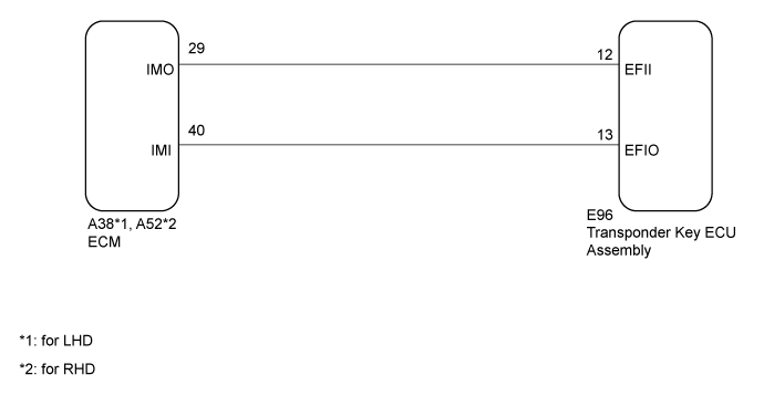
| 9.CHECK HARNESS AND CONNECTOR (TRANSPONDER KEY ECU ASSEMBLY - ECM) |
Disconnect the E96 transponder key ECU assembly connector.
Disconnect the A38*1 or A52*2 ECM connector.
- *1: for LHD
- *2: for RHD
Measure the resistance according to the value(s) in the table below.
- Standard Resistance:
for LHDTester Connection
| Condition
| Specified Condition
|
E96-12 (EFII) - A38-29 (IMO)
| Always
| Below 1 Ω
|
E96-13 (EFIO) - A38-40 (IMI)
| Always
| Below 1 Ω
|
E96-12 (EFII) - Body ground
| Always
| 10 kΩ or higher
|
E96-13 (EFIO) - Body ground
| Always
| 10 kΩ or higher
|
A38-29 (IMO) - Body ground
| Always
| 10 kΩ or higher
|
A38-40 (IMI) - Body ground
| Always
| 10 kΩ or higher
|
for RHDTester Connection
| Condition
| Specified Condition
|
E96-12 (EFII) - A52-29 (IMO)
| Always
| Below 1 Ω
|
E96-13 (EFIO) - A52-40 (IMI)
| Always
| Below 1 Ω
|
E96-12 (EFII) - Body ground
| Always
| 10 kΩ or higher
|
E96-13 (EFIO) - Body ground
| Always
| 10 kΩ or higher
|
A52-29 (IMO) - Body ground
| Always
| 10 kΩ or higher
|
A52-40 (IMI) - Body ground
| Always
| 10 kΩ or higher
|
| | REPAIR OR REPLACE HARNESS OR CONNECTOR |
|
|
| 10.CHECK TRANSPONDER KEY ECU ASSEMBLY |
Replace the transponder key ECU assembly with a new one.
- HINT:
- Refer to Service Bulletin.
- NOTICE:
- Key ID code registration is necessary when replacing the transponder key ECU assembly. Refer to Service Bulletin.
Using a registered key, turn the ignition switch to ON.
Check that the engine starts 5 seconds after the ignition switch was turned to ON.
- OK:
- Engine starts normally.
ResultResult
| Proceed to
|
OK
| A
|
NG (for 1GR-FE)
| B
|
NG (for 1VD-FTV)
| C
|
| A |
|
|
|
| END (TRANSPONDER KEY ECU ASSEMBLY WAS DEFECTIVE) |
|