Engine Immobiliser System (W/O Entry And Start System) -- Terminals Of Ecu |
| CHECK TRANSPONDER KEY AMPLIFIER |

Measure the resistance and voltage, and check for pulses according to the value(s) in the table below.
Terminal No. (Symbol) Input/Output Wiring Color Terminal Description Condition Specified Condition Related Data List Item/DTC E95-7 (AGND) - Body ground - SB - Body ground Ground Always Below 1 Ω - E95-1 (VC5) - E95-7 (AGND) Input P - SB Transponder key amplifier power supply No key in ignition key cylinder Below 1 V - E95-4 (CODE) - E95-7 (AGND) Output V - SB Demodulated signal of key code data No key in ignition key cylinder Below 1 V - E95-5 (TXCT) - E95-7 (AGND) Input LG - SB Key code output signal No key in ignition key cylinder Below 1 V - Check for pulses according to the value(s) in the table below.
Terminal No. (Symbol) Input/Output Wiring Color Terminal Description Condition Specified Condition Related Data List Item/DTC E95-1 (VC5) - E95-7 (AGND) Input P - SB Transponder key amplifier power supply Key inserted in ignition key cylinder Pulse generation
(See waveform 1)- BCC Malfunction
- Abnormal Status
- Different Encrypt Code
- Different Serial Number
E95-4 (CODE) - E95-7 (AGND) Output V - SB Demodulated signal of key code data Key inserted in ignition key cylinder Pulse generation
(See waveform 2)E95-5 (TXCT) - E95-7 (AGND) Input LG - SB Key code output signal Key inserted in ignition key cylinder Pulse generation
(See waveform 3)- BCC Malfunction
Inspect using an oscilloscope.
- NOTICE:
- The waveform shown in the illustration is an example for reference only. Noise, chattering, etc. are not shown.
Waveform 1 (Reference)
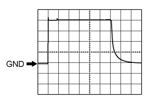
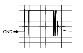
Measurement Condition Item Content Tester Connection E95-1 (VC5) - E95-7 (AGND) Tool Setting 1 V/DIV., 20 ms./DIV. Condition Key inserted in ignition key cylinder Waveform 2 (Reference)
Measurement Condition Item Content Tester Connection E95-4 (CODE) - E95-7 (AGND) Tool Setting 1 V/DIV., 20 ms./DIV. Condition Key inserted in ignition key cylinder Waveform 3 (Reference)
Measurement Condition Item Content Tester Connection E95-5 (TXCT) - E95-7 (AGND) Tool Setting 1 V/DIV., 20 ms./DIV. Condition Key inserted in ignition key cylinder


| CHECK TRANSPONDER KEY ECU ASSEMBLY |

Disconnect the E96 transponder key ECU assembly connector.
Measure the resistance and voltage according to the value(s) in the table below.
Terminal No. (Symbol) Input/Output Wiring Color Terminal Description Condition Specified Condition Related Data List Item/DTC E96-16 (GND) - Body ground - W-B - Body ground Ground Always Below 1 Ω - E96-1 (+B) - E96-16 (GND) Input B - W-B Battery Always 11 to 14 V +B E96-2 (IG) - E96-16 (GND) Input B - W-B Ignition switch Ignition switch off Below 1 V IG SW Ignition switch ON 11 to 14 V E96-3 (KSW) - E96-16 (GND) Input G - W-B Unlock warning switch No key in ignition key cylinder 10 kΩ or higher Key SW/B2780 Key inserted in ignition key cylinder Below 1 Ω Reconnect the E96 transponder key ECU connector.
Measure the resistance and voltage, and check for pulses according to the value(s) in the table below.
Terminal No. (Symbol) Input/Output Wiring Color Terminal Description Condition Specified Condition Related Data List Item/DTC E96-14 (VC5) - E96-16 (GND) Input P - W-B Transponder key amplifier power supply No key in ignition key cylinder Below 1 V - BCC Malfunction
- Abnormal Status
- Different Encrypt Code
- Different Serial Number
Key inserted in ignition key cylinder Pulse generation
(See waveform 1)E96-4 (TXCT) - E96-16 (GND) Input LG - W-B Key code output signal No key in ignition key cylinder Below 1 V Key inserted in ignition key cylinder Pulse generation
(See waveform 2)E96-15 (CODE) - E96-16 (GND) Output V - W-B Demodulated signal of key code data No key in ignition key cylinder Below 1 V Key inserted in ignition key cylinder Pulse generation
(See waveform 3)E96-13 (EFIO) - E96-16 (GND) Input R - W-B ECM output signal Ignition switch off Below 1 V E/G Start Permission Within 3 seconds after starter operates and initial combustion occurs, or within 3 seconds after ignition switch first turned to ON after battery disconnected and reconnected Pulse generation
(See waveform 4)E96-12 (EFII) - E96-16 (GND) Output W - W-B ECM input signal Within 3 seconds after starter operates and initial combustion occurs, or within 3 seconds after ignition switch first turned to ON after battery disconnected and reconnected Pulse generation
(See waveform 5)E/G Start Permission E96-9 (D) - E96-16 (GND) Input/Output R - W-B Diagnosis tester communication Always Pulse generation - E96-5 (AGND) - Body ground - SB - Body ground Transponder key amplifier ground Always Below 1 Ω - E96-8 (IND) - Body ground Output V - Body ground Security indicator signal No key in ignition key cylinder, or 20 sec. elapsed after turning the ignition switch to ACC or off (engine immobiliser system set) Pulse generation - Key in ignition key cylinder (engine immobiliser system unset) Below 1 V - BCC Malfunction
Inspect using an oscilloscope.
- NOTICE:
- The waveform shown in the illustration is an example for reference only. Noise, chattering, etc. are not shown.
Waveform 1 (Reference)
Measurement Condition Item Content Tester Connection E96-14 (VC5) - E96-16 (GND) Tool Setting 1 V/DIV., 20 ms./DIV. Condition Key inserted in ignition key cylinder Waveform 2 (Reference)
Measurement Condition Item Content Tester Connection E96-4 (TXCT) - E96-16 (GND) Tool Setting 1 V/DIV., 20 ms./DIV. Condition Key inserted in ignition key cylinder Waveform 3 (Reference)
Measurement Condition Item Content Tester Connection E96-15 (CODE) - E96-16 (GND) Tool Setting 1 V/DIV., 20 ms./DIV. Condition Key inserted in ignition key cylinder Waveform 4 (Reference)

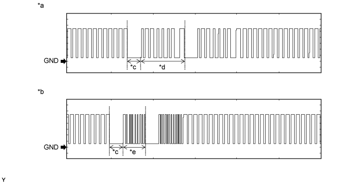
Text in Illustration *a Waveform A *b Waveform B *c Approximately 160 ms *d Approximately 510 ms *e Approximately 270 ms - - Measurement Condition Item Content Tester Connection E96-13 (EFIO) - E96-16 (GND) Tool Setting 2 V/DIV., 500 ms./DIV. Condition Within 3 seconds after starter operates and initial combustion occurs, or within 3 seconds after ignition switch first turned to ON after battery disconnected and reconnected Waveform 5 (Reference)
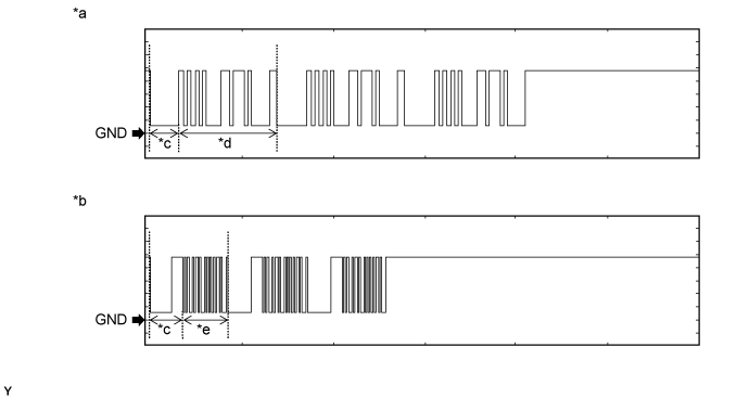
Text in Illustration *a Waveform A *b Waveform B *c Approximately 160 ms *d Approximately 510 ms *e Approximately 270 ms - - Measurement Condition Item Content Tester Connection E96-12 (EFII) - E96-16 (GND) Tool Setting 2 V/DIV., 500 ms./DIV. Condition Within 3 seconds after starter operates and initial combustion occurs, or within 3 seconds after ignition switch first turned to ON after battery disconnected and reconnected

| CHECK ECM (for 1GR-FE) |
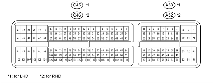
for LHD:
Measure the voltage and check for pulses according to the value(s) in the table below.
Terminal No. (Symbol) Input/Output Wiring Color Terminal Description Condition Specified Condition Related Data List Item/DTC C45-81 (E1) - Body ground - BR - Body ground Ground Always Below 1 Ω - A38-20 (BATT) - C45-81 (E1) Input L - BR +B power supply Always 11 to 14 V - A38-1 (+B2) - C45-81 (E1) Input B - BR +B power supply Ignition switch ON 11 to 14 V - A38-2 (+B) - C45-81 (E1) Input B - BR +B power supply Ignition switch ON 11 to 14 V - A38-10 (IMO) - C45-81 (E1) Input W - BR Transponder key ECU assembly communication input Ignition switch off 11 to 14 V - Transponder key ECU assembly communication input Within 3 seconds after starter operates and initial combustion occurs, or within 3 seconds after ignition switch first turned to ON after battery disconnected and reconnected. Pulse generation
(See waveform 1)- A38-11 (IMI) - C45-81 (E1) Output R - BR Transponder key ECU assembly communication output Ignition switch off 11 to 14 V - Transponder key ECU assembly communication output Within 3 seconds after starter operates and initial combustion occurs, or within 3 seconds after ignition switch first turned to ON after battery disconnected and reconnected. Pulse generation
(See waveform 2)-
for RHD:
Measure the voltage and check for pulses according to the value(s) in the table below.
Terminal No. (Symbol) Input/Output Wiring Color Terminal Description Condition Specified Condition Related Data List Item/DTC C46-81 (E1) - Body ground - BR - Body ground Ground Always Below 1 Ω - A52-20 (BATT) - C46-81 (E1) Input L - BR +B power supply Always 11 to 14 V - A52-1 (+B2) - C46-81 (E1) Input B - BR +B power supply Ignition switch ON 11 to 14 V - A52-2 (+B) - C46-81 (E1) Input B - BR +B power supply Ignition switch ON 11 to 14 V - A52-10 (IMO) - C46-81 (E1) Input W - BR Transponder key ECU assembly communication input Ignition switch off 11 to 14 V - Transponder key ECU assembly communication input Within 3 seconds after starter operates and initial combustion occurs, or within 3 seconds after ignition switch first turned to ON after battery disconnected and reconnected. Pulse generation
(See waveform 1)- A52-11 (IMI) - C46-81 (E1) Output R - BR Transponder key ECU assembly communication output Ignition switch off 11 to 14 V - Transponder key ECU assembly communication output Within 3 seconds after starter operates and initial combustion occurs, or within 3 seconds after ignition switch first turned to ON after battery disconnected and reconnected. Pulse generation
(See waveform 2)-
Inspect using an oscilloscope.
Waveform 1 (Reference)

Text in Illustration *a Waveform A *b Waveform B *c Approximately 160 ms *d Approximately 510 ms *e Approximately 270 ms - - Measurement Condition Item Content Tester Connection A38-10 (IMO) - C45-81 (E1)*1
A52-10 (IMO) - C46-81 (E1)*2Tool Setting 2 V/DIV., 500 ms./DIV. Condition Within 3 seconds after starter operates and initial combustion occurs, or within 3 seconds after ignition switch first turned to ON after battery disconnected and reconnected - *1: for LHD
- *2: for RHD
- *1: for LHD
Waveform 2 (Reference)
Text in Illustration *a Waveform A *b Waveform B *c Approximately 160 ms *d Approximately 510 ms *e Approximately 270 ms - - Measurement Condition Item Content Tester Connection A38-11 (IMI) - C45-81 (E1)*1
A52-11 (IMI) - C46-81 (E1)*2Tool Setting 2 V/DIV., 500 ms./DIV. Condition Within 3 seconds after starter operates and initial combustion occurs, or within 3 seconds after ignition switch first turned to ON after battery disconnected and reconnected - *1: for LHD
- *2: for RHD
- *1: for LHD
| CHECK ECM (for 1VD-FTV) |
for LHD:
Measure the voltage and check for pulses according to the value(s) in the table below.
Terminal No. (Symbol) Input/Output Wiring Color Terminal Description Condition Specified Condition Related Data List Item/DTC C45-81 (E1) - Body ground - BR - Body ground Ground Always Below 1 Ω - A38-20 (BATT) - C45-81 (E1) Input L - BR +B power supply Always 11 to 14 V - A38-2 (+B) - C45-81 (E1) Input B - BR +B power supply Ignition switch ON 11 to 14 V - A38-10 (IMO) - C45-81 (E1) Input W - BR Transponder key ECU assembly communication input Ignition switch off 11 to 14 V - Transponder key ECU assembly communication input Within 3 seconds after starter operates and initial combustion occurs, or within 3 seconds after ignition switch first turned to ON after battery disconnected and reconnected. Pulse generation
(See waveform 1)- A38-11 (IMI) - C45-81 (E1) Output R - BR Transponder key ECU assembly communication output Ignition switch off 11 to 14 V - Transponder key ECU assembly communication output Within 3 seconds after starter operates and initial combustion occurs, or within 3 seconds after ignition switch first turned to ON after battery disconnected and reconnected. Pulse generation
(See waveform 2)-
for RHD:
Measure the voltage and check for pulses according to the value(s) in the table below.
Terminal No. (Symbol) Input/Output Wiring Color Terminal Description Condition Specified Condition Related Data List Item/DTC C46-81 (E1) - Body ground - BR - Body ground Ground Always Below 1 Ω - A52-20 (BATT) - C46-81 (E1) Input L - BR +B power supply Always 11 to 14 V - A52-2 (+B) - C46-81 (E1) Input B - BR +B power supply Ignition switch ON 11 to 14 V - A52-10 (IMO) - C46-81 (E1) Input W - BR Transponder key ECU assembly communication input Ignition switch off 11 to 14 V - Transponder key ECU assembly communication input Within 3 seconds after starter operates and initial combustion occurs, or within 3 seconds after ignition switch first turned to ON after battery disconnected and reconnected. Pulse generation
(See waveform 1)- A52-11 (IMI) - C46-81 (E1) Output R - BR Transponder key ECU assembly communication output Ignition switch off 11 to 14 V - Transponder key ECU assembly communication output Within 3 seconds after starter operates and initial combustion occurs, or within 3 seconds after ignition switch first turned to ON after battery disconnected and reconnected. Pulse generation
(See waveform 2)-
Inspect using an oscilloscope.
Waveform 1 (Reference)
Text in Illustration *a Waveform A *b Waveform B *c Approximately 160 ms *d Approximately 510 ms *e Approximately 270 ms - - Measurement Condition Item Content Tester Connection A38-10 (IMO) - C45-81 (E1)*1
A52-10 (IMO) - C46-81 (E1)*2Tool Setting 2 V/DIV., 500 ms./DIV. Condition Within 3 seconds after starter operates and initial combustion occurs, or within 3 seconds after ignition switch first turned to ON after battery disconnected and reconnected - *1: for LHD
- *2: for RHD
- *1: for LHD
Waveform 2 (Reference)
Text in Illustration *a Waveform A *b Waveform B *c Approximately 160 ms *d Approximately 510 ms *e Approximately 270 ms - - Measurement Condition Item Content Tester Connection A38-11 (IMI) - C45-81 (E1)*1
A52-11 (IMI) - C46-81 (E1)*2Tool Setting 2 V/DIV., 500 ms./DIV. Condition Within 3 seconds after starter operates and initial combustion occurs, or within 3 seconds after ignition switch first turned to ON after battery disconnected and reconnected - *1: for LHD
- *2: for RHD
- *1: for LHD