Dtc B2273 Ignition 2 Monitor Malfunction
DESCRIPTION
WIRING DIAGRAM
INSPECTION PROCEDURE
READ VALUE USING INTELLIGENT TESTER (IG2 RELAY MONITOR (INSIDE))
CHECK WHETHER DTC OUTPUT RECURS
INSPECT FUSE (IG2 MAIN)
INSPECT INTEGRATION NO.1 RELAY (IG2 RELAY)
CHECK HARNESS AND CONNECTOR (MAIN BODY ECU - INTEGRATION RELAY (IG2 RELAY) AND BODY GROUND)
DTC B2273 Ignition 2 Monitor Malfunction |
DESCRIPTION
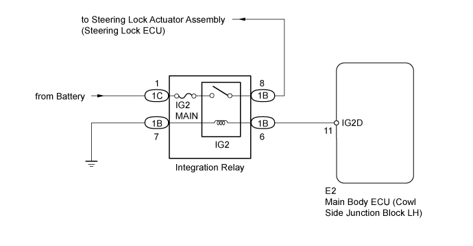
This DTC is stored when a malfunction occurs in the IG2D output circuit, which is between the integration relay (IG2 relay) actuation circuit inside the main body ECU and the integration relay (IG2 relay).DTC Code
| Detection Condition
| Trouble Area
|
B2273
| The integration relay (IG2 relay) actuation circuit inside the main body ECU or other related circuit is malfunctioning.
| - Main body ECU
- IG2 MAIN fuse
- Integration relay (IG2 relay)
- Harness or connector
|
WIRING DIAGRAM
INSPECTION PROCEDURE
| 1.READ VALUE USING INTELLIGENT TESTER (IG2 RELAY MONITOR (INSIDE)) |
Use the Data List to check if the integration relay (IG2 relay) is functioning properly.
Main BodyTester Display
| Measurement Item/Range
| Normal Condition
| Diagnostic Note
|
IG2 Relay Monitor (Inside)
| Integration relay (IG2 relay) inner relay monitor/ON or OFF
| ON: Engine switch on (IG)
OFF: Engine switch off
| -
|
- OK:
- When the engine switch is turned on (IG), ON is displayed on the tester.
| 2.CHECK WHETHER DTC OUTPUT RECURS |
Clear the DTCs (Click here).
Turn the engine switch on (IG), wait at least 10 seconds, and check whether DTC B2273 is output.
ResultResult
| Proceed to
|
No DTC output
| A
|
DTC B2273 output
| B
|
| 3.INSPECT FUSE (IG2 MAIN) |
Remove the IG2 MAIN fuse from the integration relay.
Measure the resistance according to the value(s) in the table below.
- Standard Resistance:
Tester Connection
| Condition
| Specified Condition
|
IG2 MAIN fuse
| Always
| Below 1 Ω
|
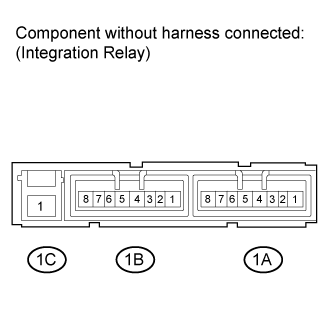
| 4.INSPECT INTEGRATION NO.1 RELAY (IG2 RELAY) |
Install the IG2 MAIN fuse to the integration relay.
Remove the integration relay from the engine room relay block.
Measure the resistance according to the value(s) in the table below.
- Standard Resistance:
Tester Connection
| Condition
| Specified Condition
|
1B-8 - 1C-1
| Battery voltage applied to terminals 1B-6 and 1B-7
| Below 1 Ω
|
1B-8 - 1C-1
| Battery voltage not applied to terminals 1B-6 and 1B-7
| 10 kΩ or higher
|
| | REPLACE INTEGRATION NO.1 RELAY (IG2 RELAY) |
|
|
| 5.CHECK HARNESS AND CONNECTOR (MAIN BODY ECU - INTEGRATION RELAY (IG2 RELAY) AND BODY GROUND) |
Disconnect the E2 main body ECU connector.
Disconnect the 1B integration relay connector.
Measure the resistance according to the value(s) in the table below.
- Standard Resistance:
Tester Connection
| Condition
| Specified Condition
|
E2-11 (IG2D) - 1B-6
| Always
| Below 1 Ω
|
1B-7 - Body ground
| Always
| Below 1 Ω
|
E2-11 (IG2D) or 1B-6 - Body ground
| Always
| 10 kΩ or higher
|
| | REPAIR OR REPLACE HARNESS OR CONNECTOR |
|
|