Dtc B2284 Brake Signal Malfunction
DESCRIPTION
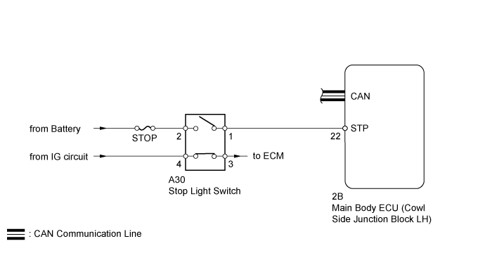
WIRING DIAGRAM
INSPECTION PROCEDURE
READ VALUE USING INTELLIGENT TESTER (STOP LIGHT SWITCH)
INSPECT FUSE (STOP)
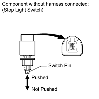
INSPECT STOP LIGHT SWITCH
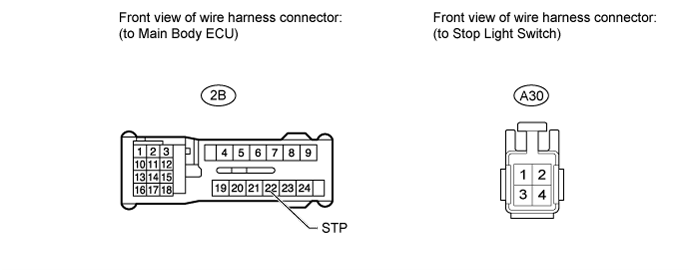
CHECK HARNESS AND CONNECTOR (MAIN BODY ECU - BATTERY AND STOP LIGHT SWITCH)
DTC B2284 Brake Signal Malfunction |
DESCRIPTION
This DTC is stored when there is an inconsistency between the circuit between the main body ECU and stop light switch, and the CAN communication signal between the main body ECU and ECM.DTC No.
| Detection Condition
| Trouble Area
|
B2284
| The circuit between the main body ECU and stop light switch, and the CAN communication signal between the main body ECU and ECM are inconsistent.
| - Main body ECU
- Stop light switch
- STOP fuse
- Harness or connector
|
WIRING DIAGRAM
INSPECTION PROCEDURE
| 1.READ VALUE USING INTELLIGENT TESTER (STOP LIGHT SWITCH) |
Use the Data List to check if the stop light switch is functioning properly.
Main BodyTester Display
| Measurement Item/Range
| Normal Condition
| Diagnostic Note
|
Stop Light SW
| Stop light switch/ON or OFF
| ON: Brake pedal depressed
OFF: Brake pedal released
| -
|
ResultResult
| Proceed to
|
Display on the intelligent tester does not change according to brake pedal operation
| A
|
Display on the intelligent tester changes according to brake pedal operation
| B
|
Remove the STOP fuse from the engine room relay block.
Measure the resistance according to the value(s) in the table below.
- Standard Resistance:
Tester Connection
| Condition
| Specified Condition
|
STOP fuse
| Always
| Below 1 Ω
|
| 3.INSPECT STOP LIGHT SWITCH |
Disconnect the A30 stop light switch connector.
Measure the resistance according to the value(s) in the table below.
- Standard Resistance:
Tester Connection
| Switch Condition
| Specified Condition
|
1 - 2
| Stop light switch pin not pushed
| Below 1 Ω
|
3 - 4
| Stop light switch pin pushed
| Below 1 Ω
|
1 - 2
| Stop light switch pin pushed
| 10 kΩ or higher
|
3 - 4
| Stop light switch pin not pushed
| 10 kΩ or higher
|
| 4.CHECK HARNESS AND CONNECTOR (MAIN BODY ECU - BATTERY AND STOP LIGHT SWITCH) |
Disconnect the 2B main body ECU connector.
Disconnect the A30 stop light switch connector.
Measure the voltage and resistance according to the value(s) in the table below.
- Standard Voltage:
Tester Connection
| Condition
| Specified Condition
|
A30-2 - Body ground
| Always
| 11 to 14 V
|
- Standard Resistance:
Tester Connection
| Condition
| Specified Condition
|
2B-22 (STP) - A30-1
| Always
| Below 1 Ω
|
2B-22 (STP) or A30-1 - Body ground
| Always
| 10 kΩ or higher
|
| | REPAIR OR REPLACE HARNESS OR CONNECTOR |
|
|