Power Door Lock Control System -- Terminals Of Ecu |
| CHECK MULTIPLEX NETWORK MASTER SWITCH ASSEMBLY |
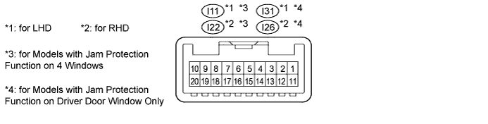
for Models with Jam Protection Function on 4 Windows
Disconnect the I11*1 or I22*2 switch connector.
- HINT:
- *1: for LHD
- *2: for RHD
Measure the voltage and resistance according to the value(s) in the table below.
Terminal No. (Symbol) Wiring Color Terminal Description Condition Specified Condition I11-12 (GND) - Body ground*1 W-B - Body ground Ground Always Below 1 Ω I11-11 (B) - I11-12 (GND)*1 L - W-B Battery power supply Always 11 to 14 V I22-12 (GND) - Body ground*2 W-B - Body ground Ground Always Below 1 Ω I22-11 (B) - I22-12 (GND)*2 L - W-B Battery power supply Always 11 to 14 V - HINT:
- *1: for LHD
- *2: for RHD
for Models with Jam Protection Function on Driver Door Window Only
Disconnect the I31*1 or I26*2 switch connector.
- HINT:
- *1: for LHD
- *2: for RHD
Measure the voltage and resistance according to the value(s) in the table below.
Terminal No. (Symbol) Wiring Color Terminal Description Condition Specified Condition I31-1 (E) - Body ground*1 W-B - Body ground Ground Always Below 1 Ω I31-6 (B) - I31-1 (E)*1 L - W-B Battery power supply Always 11 to 14 V I26-9 (E) - Body ground*2 W-B - Body ground Ground Always Below 1 Ω I26-6 (B) - I26-9 (E)*2 L - W-B Battery power supply Always 11 to 14 V - HINT:
- *1: for LHD
- *2: for RHD
| CHECK MAIN BODY ECU (COWL SIDE JUNCTION BLOCK LH) |

Disconnect the 2A, 2B and 2D ECU connectors.
Measure the voltage and resistance according to the value(s) in the table below.
If the result is not as specified, there may be a malfunction on the wire harness side.Terminal No. (Symbol) Wiring Color Terminal Description Condition Specified Condition 2B-20 (BATB) - Body ground L - Body ground Battery power supply Always 11 to 14 V 2A-1 (ACC) - Body ground B - Body ground ACC power supply Ignition switch ACC 11 to 14 V 2A-1 (ACC) - Body ground B - Body ground ACC power supply Ignition switch off Below 1 Ω 2D-62 (GND2) - Body ground W-B - Body ground Ground Always Below 1 Ω Reconnect the 2A, 2B and 2D ECU connectors.
Measure the voltage according to the value(s) in the table below.
Terminal No. (Symbol) Wiring Color Terminal Description Condition Specified Condition E1-24 (DCTY) - Body ground L*1 - Body ground
Y*2 - Body groundDriver side door courtesy switch input Driver side door open Below 1 V E1-24 (DCTY) - Body ground L*1 - Body ground
Y*2 - Body groundDriver side door courtesy switch input Ignition switch off, and driver side door courtesy switch off Pulse generation E2-21 (PCTY) - Body ground Y*1 - Body ground
L*2 - Body groundFront passenger side door courtesy switch input Front passenger side door open Below 1 V E2-21 (PCTY) - Body ground Y*1 - Body ground
L*2 - Body groundFront passenger side door courtesy switch input Ignition switch off, and passenger side door courtesy switch off Pulse generation 2C-2 (LCTY) - Body ground W - Body ground Rear door LH courtesy light switch input Rear door LH open Below 1 V 2C-2 (LCTY) - Body ground W - Body ground Rear door LH courtesy light switch input Ignition switch off, and rear LH side door courtesy switch off Pulse generation E2-7 (RCTY) - Body ground
*3G - Body ground Rear door RH courtesy light switch input Rear door RH open Below 1 V E2-7 (RCTY) - Body ground
*3G - Body ground Rear door RH courtesy light switch input Ignition switch off, and rear RH side door courtesy switch off Pulse generation E1-17 (RCTY) - Body ground
*4G - Body ground Rear door RH courtesy light switch input Rear door RH open Below 1 V E1-17 (RCTY) - Body ground
*4G - Body ground Rear door RH courtesy light switch input Ignition switch off, and rear RH side door courtesy switch off Pulse generation E2-25 (BCTY) - Body ground W - Body ground Back door courtesy light switch input Back door open Below 1 V E2-25 (BCTY) - Body ground W - Body ground Back door courtesy light switch input Ignition switch off, and back door closed Pulse generation 2D-3 (ACT+) - Body ground L - Body ground Door lock motor LOCK drive output Master switch (door control switch) or driver side door key cylinder in neutral position Below 1 V 2D-3 (ACT+) - Body ground L - Body ground Door lock motor LOCK drive output Master switch (door control switch) or driver side door key cylinder in lock position 11 to 14 V 2C-24 (ACT+) - Body ground L - Body ground Door lock motor LOCK drive output Master switch (door control switch) or driver side door key cylinder in neutral position Below 1 V 2C-24 (ACT+) - Body ground L - Body ground Door lock motor LOCK drive output Master switch (door control switch) or driver side door key cylinder in lock position 11 to 14 V E1-5 (ACTD) - Body ground B - Body ground Door lock motor UNLOCK drive output Master switch (door control switch) or driver side door key cylinder in neutral position Below 1 V E1-5 (ACTD) - Body ground B - Body ground Door lock motor UNLOCK drive output Master switch (door control switch) or driver side door key cylinder in unlock position 11 to 14 V 2D-2 (ACT-) - Body ground B - Body ground Door lock motor UNLOCK drive output Master switch (door control switch) or driver side door key cylinder in neutral position Below 1 V 2D-2 (ACT-) - Body ground B - Body ground Door lock motor UNLOCK drive output Master switch (door control switch) or driver side door key cylinder in unlock position 11 to 14 V 2C-23 (ACT-) - Body ground B - Body ground Door lock motor UNLOCK drive output Master switch (door control switch) or driver side door key cylinder in neutral position Below 1 V 2C-23 (ACT-) - Body ground B - Body ground Door lock motor UNLOCK drive output Master switch (door control switch) or driver side door key cylinder in unlock position 11 to 14 V E1-10 (UL3) - Body ground Y*1 - Body ground
L*2 - Body groundDriver side door lock key switch input Driver side door key cylinder in unlock position Below 1 V E1-10 (UL3) - Body ground Y*1 - Body ground
L*2 - Body groundDriver side door lock key switch input Ignition switch off, all doors closed and driver side door key cylinder in neutral position Pulse generation 2D-53 (L2) - Body ground LG - Body ground Driver side door lock key switch input Driver side door key cylinder in lock position Below 1 V 2D-53 (L2) - Body ground LG - Body ground Driver side door lock key switch input Ignition switch off, all doors closed and driver side door key cylinder in neutral position Pulse generation 2D-52 (UL1) - Body ground
*4W - Body ground Master switch (door control switch) input Master switch (door control switch) in unlock position Below 1 V 2D-52 (UL1) - Body ground
*4W - Body ground Master switch (door control switch) input Master switch (door control switch) in neutral position Pulse generation 2D-52 (UL1) - Body ground
*4G - Body ground Door control switch assembly input Door control switch assembly in unlock position Below 1 V 2D-52 (UL1) - Body ground
*4G - Body ground Door control switch assembly input Door control switch assembly in neutral position Pulse generation 2D-49 (L1) - Body ground
*4BE - Body ground Master switch (door control switch) input Master switch (door control switch) in unlock position Below 1 V 2D-49 (L1) - Body ground
*4BE - Body ground Master switch (door control switch) input Master switch (door control switch) in neutral position Pulse generation 2D-49 (L1) - Body ground
*4R - Body ground Door control switch assembly input Door control switch assembly in unlock position Below 1 V 2D-49 (L1) - Body ground
*4R - Body ground Door control switch assembly input Door control switch assembly in neutral position Pulse generation E1-1 (TR+) - Body ground
*3L - Body ground Back door lock motor UNLOCK drive output Master switch (door control switch) or driver side door key cylinder in neutral position Below 1 V E1-1 (TR+) - Body ground
*3L - Body ground Back door lock motor UNLOCK drive output Master switch (door control switch) or driver side door key cylinder in unlock position 11 to 14 V E1-9 (LSWD) - Body ground BR*5 - Body ground
BE*6 - Body groundDriver side door lock position switch input Driver side door unlocked Below 1 V E1-9 (LSWD) - Body ground BR*5 - Body ground
BE*6 - Body groundDriver side door lock position switch input Ignition switch off, all doors closed and driver side door locked Pulse generation E2-27 (LSWP) - Body ground Y*1 - Body ground
BR*2*5 - Body ground
BE*6 - Body groundFront passenger side door lock position switch input Front passenger side door unlocked Below 1 V E2-27 (LSWP) - Body ground Y*1 - Body ground
BR*2*5 - Body ground
BE*6 - Body groundFront passenger side door lock position switch input Ignition switch off, all doors closed and passenger side door locked Pulse generation 2C-1 (LSWL) - Body ground BR*5 - Body ground
BE*6 - Body groundRear door LH lock position switch input Rear door LH unlocked Below 1 V 2C-1 (LSWL) - Body ground BR*5 - Body ground
BE*6 - Body groundRear door LH lock position switch input Ignition switch off, all doors closed and rear door LH locked Pulse generation E2-5 (LSWR) - Body ground BR*5 - Body ground
BE*6 - Body groundRear door RH lock position switch input Rear door RH unlocked Below 1 V E2-5 (LSWR) - Body ground BR*5 - Body ground
BE*6 - Body groundRear door RH lock position switch input Ignition switch off, all doors closed and rear door RH locked Pulse generation E2-2 (LSWB) - Body ground
*4LG - Body ground Back door lock position switch input Back door unlocked Below 1 V E2-2 (LSWB) - Body ground
*4LG - Body ground Back door lock position switch input Ignition switch off, all doors closed and back door locked Pulse generation E1-26 (BDSU) - Body ground
*3L - Body ground Back door opener switch input Back door lock opener switch off Below 1 V E1-26 (BDSU) - Body ground
*3L - Body ground Back door opener switch input Back door lock opener switch on Pulse generation - HINT:
- *1: for LHD
- *2: for RHD
- *3: w/ Entry and Start System
- *4: w/o Entry and Start System
- *5: for GRJ200L-GNANKC, URJ202L-GNTEKC
- *6: except GRJ200L-GNANKC, URJ202L-GNTEKC
| CHECK DOUBLE LOCK DOOR CONTROL RELAY (w/ Double Locking Function) |

Disconnect the E86 double lock door control relay connector.
Measure the voltage according to the value(s) in the table below.
If the result is not as specified, there may be a malfunction on the wire harness side.Terminal No. (Symbol) Wiring Color Terminal Description Condition Specified Condition E86-1 (+B) - E86-14 (GND) B - W-B Battery power supply Always 11 to 14 V E86-7 (CPUB) - E86-14 (GND) R - W-B ECU power supply Always 11 to 14 V E86-14 (GND) - Body ground W-B - Body ground Ground Always Below 1 V Reconnect the E86 double lock door control relay connector.
Measure the voltage and resistance according to the value(s) in the table below.
Terminal No. (Symbol) Wiring Color Terminal Description Condition Specified Condition E86-4 (ACTR) - E86-14 (GND) P - W-B All door double lock motor off signal Door lock set → unset Below 1 V → 11 to 14 V → Below 1 V E86-3 (ACTS) - E86-14 (GND) G - W-B All door double lock motor on signal Door lock unset → set Below 1 V → 11 to 14 V → Below 1 V E86-5 (DLPD) - E86-14 (GND) BR*1 - Body ground
BE*2 - Body groundDouble lock position switch signal Double lock set Below 1 Ω E86-5 (DLPD) - E86-14 (GND) BR*1 - Body ground
BE*2 - Body groundDouble lock position switch signal Double lock unset 10 kΩ or higher E86-6 (DLPP) - E86-14 (GND) GR - W-B Double lock position switch signal Double lock set Below 1 Ω E86-6 (DLPP) - E86-14 (GND) GR - W-B Double lock position switch signal Double lock unset 10 kΩ or higher E86-11 (DLPR) - E86-14 (GND) Y*1 - W-B
SB*2 - W-BDouble lock position switch signal Double lock set Below 1 Ω E86-11 (DLPR) - E86-14 (GND) Y*1 - W-B
SB*2 - W-BDouble lock position switch signal Double lock unset 10 kΩ or higher E86-12 (DLPL) - E86-14 (GND) LG - W-B Double lock position switch signal Double lock set Below 1 Ω E86-12 (DLPL) - E86-14 (GND) LG - W-B Double lock position switch signal Double lock unset 10 kΩ or higher - HINT:
- *1: for GRJ200L-GNANKC, URJ202L-GNTEKC
- *2: except GRJ200L-GNANKC, URJ202L-GNTEKC