CHECK FOR OPEN IN CAN BUS WIRE (ECM CAN MAIN WIRE)
CHECK HARNESS AND CONNECTOR (ECM - BATTERY AND BODY GROUND)
CAN COMMUNICATION SYSTEM (for LHD with Central Gateway ECU) - ECM Communication Stop Mode |
DESCRIPTION
| Detection Item | Symptom | Trouble Area |
| ECM Communication Stop Mode | Either Condition is met:
|
|
WIRING DIAGRAM
INSPECTION PROCEDURE
- NOTICE:
- Because the order of diagnosis is important to allow correct diagnosis, make sure to begin troubleshooting using How to Proceed with Troubleshooting when CAN communication system related DTCs are output (Click here).
- Before measuring the resistance of the CAN bus, turn the ignition switch off and leave the vehicle for 1 minute or more without operating the key, switches or opening or closing the doors. After that, disconnect the cable from the negative (-) battery terminal and leave the vehicle for 1 minute or more before measuring the resistance.
- After turning the ignition switch off, waiting time may be required before disconnecting the cable from the battery terminal. Therefore, make sure to read the disconnecting the cable from the battery terminal notice before proceeding with work (Click here).
- Inspect the fuses for circuits related to this system before performing the following inspection procedure.
- After performing repairs, perform the DTC check procedure and confirm that the DTCs are not output again.
- DTC check procedure: Allow the radar cruise control system (vehicle control mode) to operate for 1 second or more.
- After the repair, perform CAN Bus Check and check that all the ECUs and sensors connected to the CAN communication system are displayed (Click here).
- HINT:
- Operating the ignition switch, any switches or any doors triggers related ECU and sensor communication with the CAN, which causes resistance variation.
- Even after DTCs are cleared, if a DTC is stored again after driving the vehicle for a while, the malfunction may be occurring due to vibration of the vehicle. In such a case, wiggling the ECUs or wire harness while performing the inspection below may help determine the cause of the malfunction.
| 1.CHECK FOR OPEN IN CAN BUS WIRE (ECM CAN MAIN WIRE) |
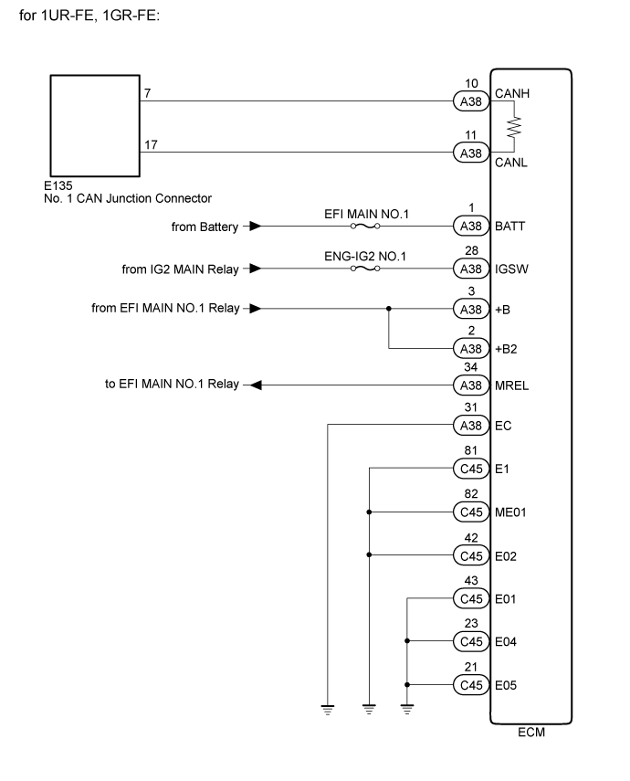
for 1UR-FE, 1GR-FE:
Disconnect the cable from the negative (-) battery terminal.
Disconnect the ECM connector.
Measure the resistance according to the value(s) in the table below.
- Standard Resistance:
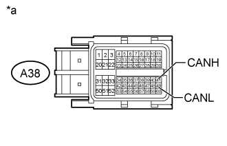
Tester Connection Condition Specified Condition A38-10 (CANH) - A38-11 (CANL) Cable disconnected from negative (-) battery terminal 108 to 132 Ω
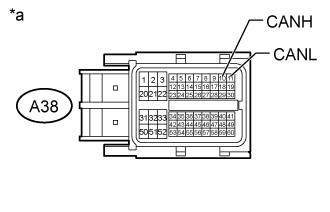
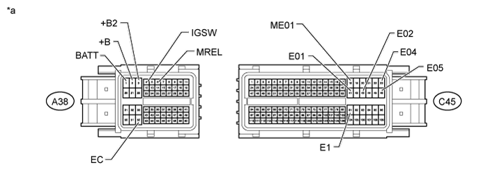
Text in Illustration *a Front view of wire harness connector
(to ECM)
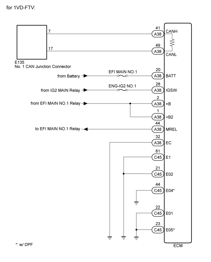
for 1VD-FTV:
Disconnect the cable from the negative (-) battery terminal.
Disconnect the ECM connector.
Measure the resistance according to the value(s) in the table below.
- Standard Resistance:
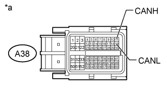
Tester Connection Condition Specified Condition A38-41 (CANH) - A38-49 (CANL) Cable disconnected from negative (-) battery terminal 108 to 132 Ω
Text in Illustration *a Front view of wire harness connector
(to ECM)
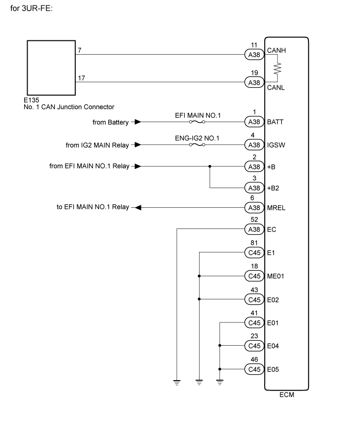
for 3UR-FE:
Disconnect the cable from the negative (-) battery terminal.
Disconnect the ECM connector.
Measure the resistance according to the value(s) in the table below.
- Standard Resistance:
Tester Connection Condition Specified Condition A38-11 (CANH) - A38-19 (CANL) Cable disconnected from negative (-) battery terminal 108 to 132 Ω
Text in Illustration *a Front view of wire harness connector
(to ECM)
|
| ||||
| OK | |
| 2.CHECK HARNESS AND CONNECTOR (ECM - BATTERY AND BODY GROUND) |
for 1UR-FE, 1GR-FE:
Connect the cable to the negative (-) battery terminal.
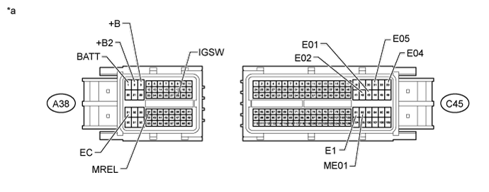
Text in Illustration *a Front view of wire harness connector
(to ECM)- - - NOTICE:
- When connecting the cable, some systems need to be initialized after the cable is reconnected (Click here).
Disconnect the ECM connector.
Measure the voltage according to the value(s) in the table below.
- Standard Voltage:
Tester Connection Condition Specified Condition A38-1 (BATT) - Body ground Always 11 to 14 V A38-3 (+B) - Body ground Battery positive (+) voltage applied to terminal A38-34 (MREL) 11 to 14 V A38-2 (+B2) - Body ground Battery positive (+) voltage applied to terminal A38-34 (MREL) 11 to 14 V A38-28 (IGSW) - Body ground Ignition switch ON 11 to 14 V
Measure the resistance according to the value(s) in the table below.
- Standard Resistance:
Tester Connection Condition Specified Condition A38-31 (EC) - Body ground Always Below 1 Ω C45-42 (E02) - Body ground Always Below 1 Ω C45-43 (E01) - Body ground Always Below 1 Ω C45-82 (ME01) - Body ground Always Below 1 Ω C45-81 (E1) - Body ground Always Below 1 Ω C45-23 (E04) - Body ground Always Below 1 Ω C45-21 (E05) - Body ground Always Below 1 Ω
for 1VD-FTV:
Connect the cable to the negative (-) battery terminal.
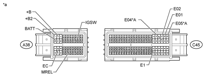
Text in Illustration *A w/ DPF - - *a Front view of wire harness connector
(to ECM)- - - NOTICE:
- When connecting the cable, some systems need to be initialized after the cable is reconnected (Click here).
Disconnect the ECM connector.
Measure the voltage according to the value(s) in the table below.
- Standard Voltage:
Tester Connection Condition Specified Condition A38-20 (BATT) - Body ground Always 11 to 14 V A38-2 (+B) - Body ground Battery positive (+) voltage applied to terminal A38-44 (MREL) 11 to 14 V A38-1 (+B2) - Body ground Battery positive (+) voltage applied to terminal A38-44 (MREL) 11 to 14 V A38-28 (IGSW) - Body ground Ignition switch ON 11 to 14 V
Measure the resistance according to the value(s) in the table below.
- Standard Resistance:
Tester Connection Condition Specified Condition A38-32 (EC) - Body ground Always Below 1 Ω C45-21 (E02) - Body ground Always Below 1 Ω C45-22 (E01) - Body ground Always Below 1 Ω C45-81 (E1) - Body ground Always Below 1 Ω C45-44 (E04) - Body ground* Always Below 1 Ω C45-23 (E05) - Body ground* Always Below 1 Ω
- *: w/ DPF
for 3UR-FE:
Connect the cable to the negative (-) battery terminal.
Text in Illustration *a Front view of wire harness connector
(to ECM)- - - NOTICE:
- When connecting the cable, some systems need to be initialized after the cable is reconnected (Click here).
Disconnect the ECM connector.
Measure the voltage according to the value(s) in the table below.
- Standard Voltage:
Tester Connection Condition Specified Condition A38-1 (BATT) - Body ground Always 11 to 14 V A38-2 (+B) - Body ground Battery positive (+) voltage applied to terminal A38-6 (MREL) 11 to 14 V A38-3 (+B2) - Body ground Battery positive (+) voltage applied to terminal A38-6 (MREL) 11 to 14 V A38-4 (IGSW) - Body ground Ignition switch ON 11 to 14 V
Measure the resistance according to the value(s) in the table below.
- Standard Resistance:
Tester Connection Condition Specified Condition A38-52 (EC) - Body ground Always Below 1 Ω C45-43 (E02) - Body ground Always Below 1 Ω C45-41 (E01) - Body ground Always Below 1 Ω C45-18 (ME01) - Body ground Always Below 1 Ω C45-81 (E1) - Body ground Always Below 1 Ω C45-23 (E04) - Body ground Always Below 1 Ω C45-46 (E05) - Body ground Always Below 1 Ω
Result Result Proceed to OK (for 1UR-FE) A OK (for 1VD-FTV) B OK (for 1GR-FE) C OK (for 3UR-FE) D NG E
|
| ||||
|
| ||||
|
| ||||
|
| ||||
| A | ||
| ||