Lin Communication System Terminals Of Ecu
Networking. Land Cruiser. Urj200, 202 Grj200 Vdj200
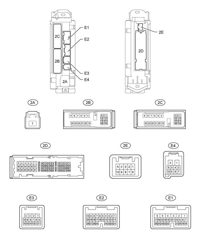
CHECK MAIN BODY ECU (COWL SIDE JUNCTION BLOCK LH)
CHECK MASTER SWITCH (for Models with Jam Protection Function on 4 Windows)
CHECK FRONT POWER WINDOW REGULATOR MOTOR LH
CHECK FRONT POWER WINDOW REGULATOR MOTOR ASSEMBLY RH
CHECK REAR POWER WINDOW REGULATOR MOTOR ASSEMBLY LH (for Models with Jam Protection Function on 4 Windows)
CHECK REAR POWER WINDOW REGULATOR MOTOR ASSEMBLY RH (for Models with Jam Protection Function on 4 Windows)
CHECK SLIDING ROOF ECU (w/ Sliding Roof System)
CHECK CERTIFICATION ECU (SMART KEY ECU ASSEMBLY)
CHECK ID CODE BOX (IMMOBILISER CODE ECU)
CHECK STEERING LOCK ECU
CHECK AIR CONDITIONING AMPLIFIER (for 4-ZONE Type)
CHECK AIR CONDITIONING AMPLIFIER (except 4-ZONE Type)
CHECK FRONT AIR CONDITIONING CONTROL PANEL (w/o Navigation System)
CHECK REAR AIR CONDITIONING CONTROL PANEL
CHECK RAIN SENSOR (w/ Rain Sensor)
CHECK WINDSHIELD WIPER ECU (w/ Rain Sensor)
Lin Communication System -- Terminals Of Ecu |
| CHECK MAIN BODY ECU (COWL SIDE JUNCTION BLOCK LH) |
Disconnect the 2D, E1, E2 and E3 ECU connectors.
Measure the resistance and voltage according to the value(s) in the table below.
Terminal No. (Symbol)
| Wiring Color
| Terminal Description
| Condition
| Specified Condition
|
2D-62 (GND2) - Body ground
| W-B - Body ground
| Ground
| Always
| Below 1 Ω
|
E3-1 (GND3) - Body ground
| BR - Body ground
| Ground
| Always
| Below 1 Ω
|
E2-1 (AM2) - 2D-62 (GND2)
| W - W-B
| Battery power supply
| Always
| 11 to 14 V
|
E1-6 (AM1) - 2D-62 (GND2)
| W - W-B
| Battery power supply
| Always
| 11 to 14 V
|
If the result is not as specified, there may be a malfunction on the wire harness side.
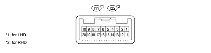
| CHECK MASTER SWITCH (for Models with Jam Protection Function on 4 Windows) |
Disconnect the I11*1 or I22*2 master switch connector.
Measure the resistance and voltage according to the value(s) in the table below.
- HINT:
- *1: for LHD
- *2: for RHD
for LHDTerminal No. (Symbol)
| Wiring Color
| Terminal Description
| Condition
| Specified Condition
|
I11-11 (B) - I11-12 (GND)
| L - W-B
| Ignition power supply
| Ignition switch off
| Below 1 Ω
|
I11-11 (B) - I11-12 (GND)
| L - W-B
| Ignition power supply
| Ignition switch ON
| 11 to 14 V
|
I11-12 (GND) - Body ground
| W-B - Body ground
| Ground
| Always
| Below 1 Ω
|
for RHDTerminal No. (Symbol)
| Wiring Color
| Terminal Description
| Condition
| Specified Condition
|
I22-11 (B) - I22-12 (GND)
| L - W-B
| Ignition power supply
| Ignition switch off
| Below 1 Ω
|
I22-11 (B) - I22-12 (GND)
| L - W-B
| Ignition power supply
| Ignition switch ON
| 11 to 14 V
|
I22-12 (GND) - Body ground
| W-B - Body ground
| Ground
| Always
| Below 1 Ω
|
If the result is not as specified, there may be a malfunction on the wire harness side.
| CHECK FRONT POWER WINDOW REGULATOR MOTOR LH |
Disconnect the I12 motor connector.
Measure the resistance and voltage according to the value(s) in the table below.
Terminal No. (Symbol)
| Wiring Color
| Terminal Description
| Condition
| Specified Condition
|
I12-2 (B) - I12-1 (GND)
| L - W-B
| Battery power supply
| Always
| 11 to 14 V
|
I12-1 (GND) - Body ground
| W-B - Body ground
| Ground
| Always
| Below 1 Ω
|
If the result is not as specified, there may be a malfunction on the wire harness side.
| CHECK FRONT POWER WINDOW REGULATOR MOTOR ASSEMBLY RH |
Disconnect the I4 motor connector.
Measure the resistance and voltage according to the value(s) in the table below.
Terminal No. (Symbol)
| Wiring Color
| Terminal Description
| Condition
| Specified Condition
|
I4-2 (B) - I4-1 (GND)
| L - W-B
| Battery power supply
| Always
| 11 to 14 V
|
I4-1 (GND) - Body ground
| W-B - Body ground
| Ground
| Always
| Below 1 Ω
|
If the result is not as specified, there may be a malfunction on the wire harness side.
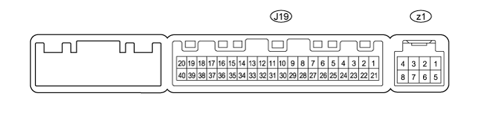
| CHECK REAR POWER WINDOW REGULATOR MOTOR ASSEMBLY LH (for Models with Jam Protection Function on 4 Windows) |
Disconnect the J11 motor connector.
Measure the resistance and voltage according to the value(s) in the table below.
Terminal No. (Symbol)
| Wiring Color
| Terminal Description
| Condition
| Specified Condition
|
J11-2 (B) - J11-1 (GND)
| L - W-B
| Battery power supply
| Always
| 11 to 14 V
|
J11-1 (GND) - Body ground
| W-B - Body ground
| Ground
| Always
| Below 1 Ω
|
If the result is not as specified, there may be a malfunction on the wire harness side.
| CHECK REAR POWER WINDOW REGULATOR MOTOR ASSEMBLY RH (for Models with Jam Protection Function on 4 Windows) |
Disconnect the J4 motor connector.
Measure the resistance and voltage according to the value(s) in the table below.
Terminal No. (Symbol)
| Wiring Color
| Terminal Description
| Condition
| Specified Condition
|
J4-2 (B) - J4-1 (GND)
| L - W-B
| Battery power supply
| Always
| 11 to 14 V
|
J4-1 (GND) - Body ground
| W-B - Body ground
| Ground
| Always
| Below 1 Ω
|
If the result is not as specified, there may be a malfunction on the wire harness side.
| CHECK SLIDING ROOF ECU (w/ Sliding Roof System) |
Disconnect the R5 ECU connector.
Measure the resistance and voltage according to the value(s) in the table below.
Terminal No. (Symbol)
| Wiring Color
| Terminal Description
| Condition
| Specified Condition
|
R5-1 (B) - R5-2 (E)
| L - W-B
| Battery power supply
| Always
| 11 to 14 V
|
R5-2 (E) - Body ground
| W-B - Body ground
| Ground
| Always
| Below 1 Ω
|
If the result is not as specified, there may be a malfunction on the wire harness side.
| CHECK CERTIFICATION ECU (SMART KEY ECU ASSEMBLY) |
Disconnect the E29 ECU connector.
Measure the resistance and voltage according to the value(s) in the table below.
Terminal No. (Symbol)
| Wiring Color
| Terminal Description
| Condition
| Specified Condition
|
E29-1 (+B) - E29-17 (E)
| B - W-B
| Battery power supply
| Always
| 11 to 14 V
|
E29-17 (E) - Body ground
| W-B - Body ground
| Ground
| Always
| Below 1 Ω
|
If the result is not as specified, there may be a malfunction on the wire harness side.
| CHECK ID CODE BOX (IMMOBILISER CODE ECU) |
Disconnect the E28 ECU connector.
Measure the resistance and voltage according to the value(s) in the table below.
Terminal No. (Symbol)
| Wiring Color
| Terminal Description
| Condition
| Specified Condition
|
E28-1 (+B) - E28-8 (GND)
| B - W-B
| Battery power supply
| Always
| 11 to 14 V
|
E28-8 (GND) - Body ground
| W-B - Body ground
| Ground
| Always
| Below 1 Ω
|
If the result is not as specified, there may be a malfunction on the wire harness side.
Disconnect the E26 ECU connector.
Measure the resistance and voltage according to the value(s) in the table below.
Terminal No. (Symbol)
| Wiring Color
| Terminal Description
| Condition
| Specified Condition
|
E26-7 (B) - E26-1 (GND)
| R - W-B
| Battery power supply
| Always
| 11 to 14 V
|
E26-1 (GND) - Body ground
| W-B - Body ground
| Ground
| Always
| Below 1 Ω
|
If the result is not as specified, there may be a malfunction on the wire harness side.
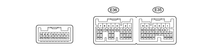
| CHECK AIR CONDITIONING AMPLIFIER (for 4-ZONE Type) |
Disconnect the E36 amplifier connector.
Measure the resistance and voltage according to the value(s) in the table below.
Terminal No. (Symbol)
| Wiring Color
| Terminal Description
| Condition
| Specified Condition
|
E36-5 (IG+) - E36-1 (GND)
| G - W-B
| IG power supply
| Ignition switch off
| Below 1 V
|
E36-5 (IG+) - E36-1 (GND)
| G - W-B
| IG power supply
| Ignition switch ON
| 11 to 14 V
|
E36-6 (+B1) - E36-1 (GND)
| R - W-B
| Battery power supply
| Always
| 11 to 14 V
|
E36-7 (+B2) - E36-1 (GND)
| R - W-B
| Battery power supply
| Always
| 11 to 14 V
|
E36-1 (GND) - Body ground
| W-B - Body ground
| Ground
| Always
| Below 1 Ω
|
If the result is not as specified, there may be a malfunction on the wire harness side.
| CHECK AIR CONDITIONING AMPLIFIER (except 4-ZONE Type) |
Disconnect the E81 amplifier connector.
Measure the resistance and voltage according to the value(s) in the table below.
Terminal No. (Symbol)
| Wiring Color
| Terminal Description
| Condition
| Specified Condition
|
E81-21 (+B) - E81-14 (GND)
| R - W-B
| Battery power supply
| Always
| 11 to 14 V
|
E81-1 (IG+) - E81-14 (GND)
| G - W-B
| IG power supply
| Ignition switch ON
| 11 to 14 V
|
E81-1 (IG+) - E81-14 (GND)
| G - W-B
| IG power supply
| Ignition switch off
| Below 1 V
|
E81-14 (GND) - Body ground
| W-B - Body ground
| Ground
| Always
| Below 1 Ω
|
If the result is not as specified, there may be a malfunction on the wire harness side.
| CHECK FRONT AIR CONDITIONING CONTROL PANEL (w/o Navigation System) |
Disconnect the F10 panel connector.
Measure the resistance and voltage according to the value(s) in the table below.
Terminal No. (Symbol)
| Wiring Color
| Terminal Description
| Condition
| Specified Condition
|
F10-7 (IG+) - F10-1 (GND)
| G - W-B
| IG power supply
| Ignition switch ON
| 11 to 14 V
|
F10-1 (GND) - Body ground
| W-B - Body ground
| Ground
| Always
| Below 1 Ω
|
If the result is not as specified, there may be a malfunction on the wire harness side.
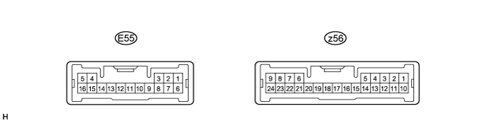
| CHECK REAR AIR CONDITIONING CONTROL PANEL |
Disconnect the E55 panel connector.
Measure the resistance and voltage according to the value(s) in the table below.
Terminal No. (Symbol)
| Wiring Color
| Terminal Description
| Condition
| Specified Condition
|
E55-6 (IG) - E55-1 (E)
| G - W-B
| IG power supply
| Ignition switch ON
| 11 to 14 V
|
E55-1 (E) - Body ground
| W-B - Body ground
| Ground
| Always
| Below 1 Ω
|
If the result is not as specified, there may be a malfunction on the wire harness side.
| CHECK RAIN SENSOR (w/ Rain Sensor) |
Disconnect the R11 rain sensor connector.
Measure the voltage according to the value(s) in the table below.
Terminal No. (Symbol)
| Wiring Color
| Terminal Description
| Condition
| Specified Condition
|
R11-4 (SIG) - Body ground
| G - Body ground
| IG signal circuit (to IG relay)
| Ignition switch off
| Below 1 V
|
Ignition switch ON
| 11 to 14 V
|
R11-1 (ES) - Body ground
| W - Body ground
| Ground circuit
| Always
| Below 1 V
|
If the result is not as specified, there may be a malfunction on the wire harness side.
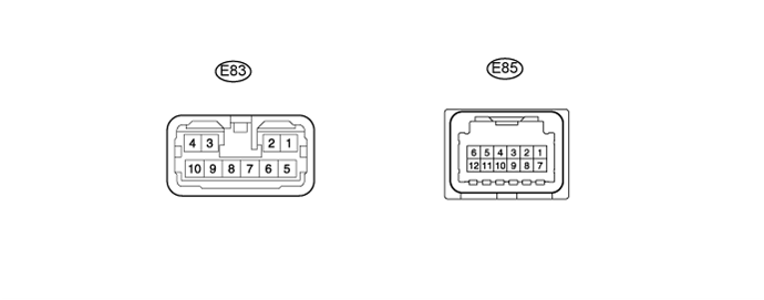
| CHECK WINDSHIELD WIPER ECU (w/ Rain Sensor) |
Disconnect the E83 and E85 ECU connectors.
Measure the voltage and resistance according to the value(s) in the table below.
Terminal No. (Symbol)
| Wiring Color
| Terminal Description
| Condition
| Specified Condition
|
E83-5 (IG1l) - E83-6 (ES)
| G - L
| Power source
| Ignition switch ON
| 11 to 14 V
|
E85-10 (E) - Body ground
| W-B - Body ground
| Power ground
| Always
| Below 1 Ω
|
If the result is not as specified, there may be a malfunction on the wire harness side.