DISCONNECT CABLE FROM NEGATIVE BATTERY TERMINAL (w/o Door Control Battery)
REMOVE NO. 1 INSTRUMENT PANEL UNDER COVER SUB-ASSEMBLY (w/ Cover)
REMOVE LOWER INSTRUMENT PANEL SUB-ASSEMBLY (w/o Driver Side Knee Airbag)
REMOVE DRIVER SIDE KNEE AIRBAG ASSEMBLY (w/ Driver Side Knee Airbag)
Main Body Ecu (For Lhd) -- Removal |
| 1. PRECAUTION |
- NOTICE:
- After turning the ignition switch off, waiting time may be required before disconnecting the cable from the battery terminal. Therefore, make sure to read the disconnecting the cable from the battery terminal notice before proceeding with work (Click here).
| 2. DISCONNECT CABLE FROM NEGATIVE BATTERY TERMINAL (w/o Door Control Battery) |
- CAUTION:
- Wait at least 90 seconds after disconnecting the cable from the negative (-) battery terminal to disable the SRS system.
- NOTICE:
- When disconnecting the cable, some systems need to be initialized after the cable is reconnected (Click here)
| 3. DISCHARGE DOOR CONTROL BATTERY AND DISCONNECT CABLE FROM NEGATIVE BATTERY TERMINAL (w/ Door Control Battery) |
- CAUTION:
- Wait at least 90 seconds after disconnecting the cable from the negative (-) battery terminal to disable the SRS system.
- NOTICE:
- Make sure to perform this procedure with the power supply of the battery and door control battery cut to prevent damage during removal and installation of the instrument panel junction block assembly.
- Make sure to perform the following procedures, and then perform removal and installation of the instrument panel junction block assembly with the power supply from the battery and door control battery cut.
- When disconnecting the cable, some systems need to be initialized after the cable is reconnected (Click here).
- HINT:
- When the ignition switch is turned off after the door control battery is fully charged, the door control battery becomes completely discharged due to self-discharge within approximately 30 minutes.
- Approximately 90 seconds after the ignition switch is turned on (IG), the door control battery becomes fully charged.
- When approximately 30 minutes or more elapse after the ignition switch is turned off, the Active Test may not be able to be performed.
Turn the ignition switch off.
Connect the GTS to the DLC3.
Turn the GTS on.
Enter the following menus: Body Electrical / Main Body / Active Test.
- NOTICE:
- Do not perform the Active Test at this time.
Disconnect the cable from the negative (-) battery terminal.
Repeat the "Shock Detection Unlock" Active Test until the multiplex network body ECU (main body ECU) communication lost error "Lost communication with vehicle" appears on the GTS display.
- NOTICE:
- When the door control battery becomes completely discharged and the power supply is cut, the multiplex network body ECU (main body ECU) communication lost error "Lost communication with vehicle" appears on the GTS display.
- The number of times the Active Test can be performed depends on the charge condition of the door control battery.
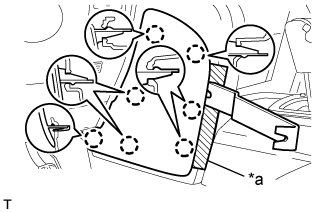
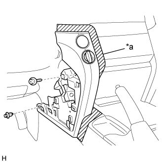
| 4. REMOVE INSTRUMENT SIDE PANEL LH |
 |
Put protective tape around the instrument side panel LH.
Text in Illustration *a Protective Tape
Using a moulding remover A, detach the 6 claws and remove the instrument side panel LH.
| 5. REMOVE FRONT DOOR SCUFF PLATE LH |
 |
Detach the 7 claws and 4 clips, and remove the front door scuff plate LH.
| 6. REMOVE NO. 2 INSTRUMENT PANEL FINISH PANEL CUSHION |
for Type A:
Put protective tape around the No. 2 instrument panel finish panel cushion.
Text in Illustration *a Protective Tape Using a moulding remover B, detach the 4 claws and 3 clips and remove the No. 2 instrument panel finish panel cushion.
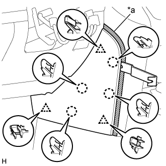
for Type B:
Put protective tape around the No. 2 instrument panel finish panel cushion.
Text in Illustration *a Protective Tape Using a moulding remover, detach the 7 claws and remove the No. 2 instrument panel finish panel cushion.
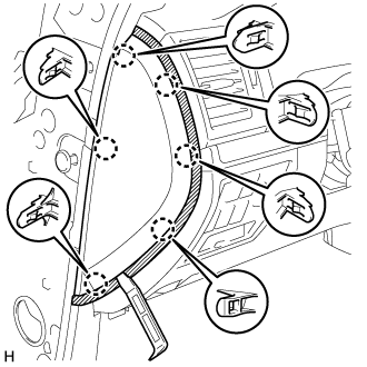
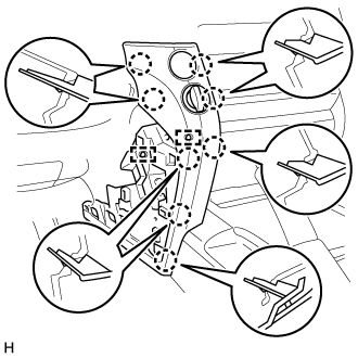
| 7. REMOVE LOWER INSTRUMENT PANEL PAD SUB-ASSEMBLY LH |
for Type A:
Put protective tape around the lower instrument panel pad sub-assembly LH.
Text in Illustration *a Protective Tape Remove the clip and screw.
Detach the 11 claws and guide.
Disconnect the connector and detach the clamps and remove the lower instrument panel pad sub-assembly LH.
for Type B:
Put protective tape around the lower instrument panel pad sub-assembly LH.
Text in Illustration *a Protective Tape Remove the clip and screw.
Detach the 8 claws and 2 guides and remove the lower instrument panel pad sub-assembly LH.
| 8. REMOVE NO. 1 INSTRUMENT CLUSTER FINISH PANEL GARNISH |
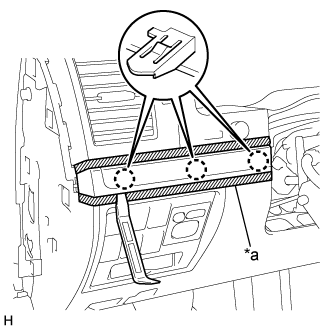 |
Put protective tape around the No. 1 instrument cluster finish panel garnish.
Text in Illustration *a Protective Tape
Using a moulding remover A, detach the 3 claws and remove the No. 1 instrument cluster finish panel garnish.
| 9. REMOVE NO. 2 INSTRUMENT CLUSTER FINISH PANEL GARNISH |
 |
Put protective tape around the No. 2 instrument cluster finish panel garnish.
Text in Illustration *a Protective Tape
Using a moulding remover A, detach the 2 claws and remove the No. 2 instrument cluster finish panel garnish.
| 10. REMOVE NO. 1 INSTRUMENT PANEL UNDER COVER SUB-ASSEMBLY (w/ Cover) |
 |
Remove the 2 screws <A>.
Text in Illustration *a Screw <A>
Detach the 3 claws.
Disconnect the connector and remove the No. 1 instrument panel under cover sub-assembly.
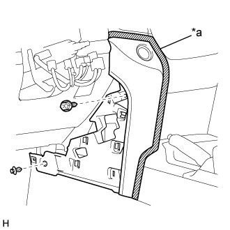
| 11. REMOVE COWL SIDE TRIM BOARD LH |
 |
Remove the cap nut.
Text in Illustration *a Cap Nut
Detach the 2 clips and remove the cowl side trim board LH.
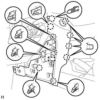
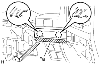
| 12. REMOVE LOWER NO. 1 INSTRUMENT PANEL FINISH PANEL |
 |
Using a screwdriver, detach the 2 claws and open the hole cover.
- HINT:
- Tape the screwdriver tip before use.
Text in Illustration *a Protective Tape
Put protective tape around the lower No. 1 instrument panel finish panel.
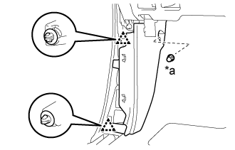
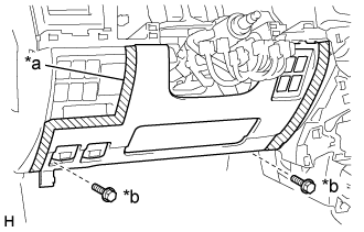 |
Remove the 2 bolts <B>.
Text in Illustration *a Protective Tape *b Bolt <B>
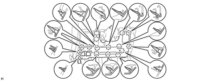
w/ Driver Side Knee Airbag:
Detach the 16 claws.
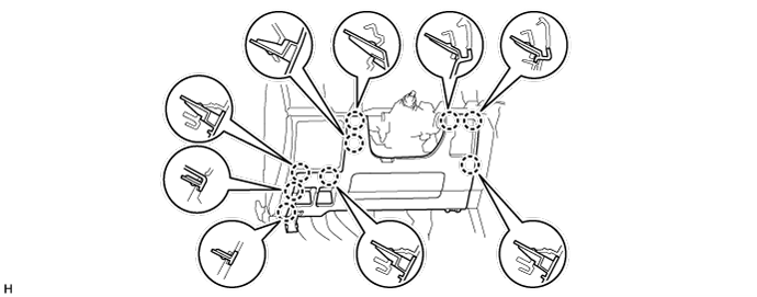
w/o Driver Side Knee Airbag:
Detach the 9 claws.
for Automatic Air Conditioning System:
Detach the 2 claws and remove the room temperature sensor.

Detach the 2 claws and disconnect the 2 control cables.
 |
Disconnect the connectors and remove the lower No. 1 instrument panel finish panel.
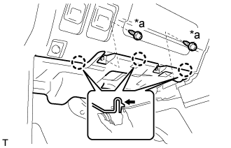
| 13. REMOVE LOWER INSTRUMENT PANEL SUB-ASSEMBLY (w/o Driver Side Knee Airbag) |
 |
Detach the 2 claws and disconnect the DLC3.
Remove the 5 bolts <B> and lower instrument panel sub-assembly.
Text in Illustration *a Bolt <B>
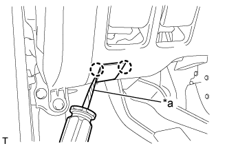
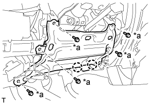
| 14. REMOVE DRIVER SIDE KNEE AIRBAG ASSEMBLY (w/ Driver Side Knee Airbag) |
Remove the 5 bolts and driver side knee airbag assembly.
 |
Using a screwdriver, release the connector lock and disconnect the airbag connector.
Text in Illustration *a Connector Lock 
Protective Tape - NOTICE:
- When handling the airbag connector, take care not to damage the airbag wire harness.
| 15. REMOVE COWL SIDE JUNCTION BLOCK LH |
Disconnect each connector.
Text in Illustration *A w/ VGRS 
Connector 
Connector with Lock Lever Protective Tape
 |
Disconnect the connector with lock lever.
- HINT:
- Use the same procedure to disconnect the connector with lock lever on the other side.
Using a screwdriver, insert the lock lever to detach the claw.
- HINT:
- Tape the screwdriver tip before use.
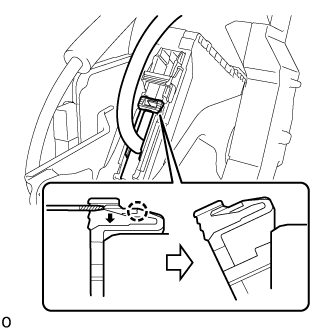
Tilt the lock lever and disconnect the connector.
Remove the bolt and 2 nuts and cowl side junction block LH.
 |
Disconnect the connector with lock lever.
Using a screwdriver, insert the lock lever to detach the claw.
- HINT:
- Tape the screwdriver tip before use.
Text in Illustration Protective Tape Tilt the lock lever and disconnect the connector.
 |
Detach the claw and slide the connector lock.
 |
Disconnect the connector with lock lever.
Using a screwdriver, insert the lock lever to detach the claw.
- HINT:
- Tape the screwdriver tip before use.
Text in Illustration Protective Tape Tilt the lock lever and disconnect the connector.
 |
| 16. REMOVE STEERING CONTROL ECU (w/ VGRS) |
Remove the 2 bolts, 2 claws and steering control ECU from the junction block.
 |
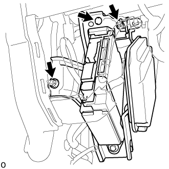
| 17. REMOVE JUNCTION BLOCK BRACKET |
Remove the bolt.
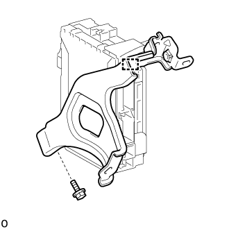 |
Detach the guide and remove the junction block bracket.
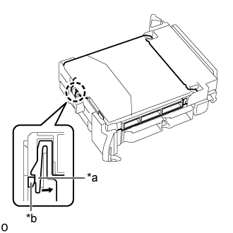
| 18. REMOVE MAIN BODY ECU (MULTIPLEX NETWORK BODY ECU) |
- NOTICE:
- If the main body ECU (multiplex network body ECU) is replaced, replace it with a new one.
- If the main body ECU (multiplex network body ECU) is replaced, refer to service bulletin.
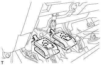
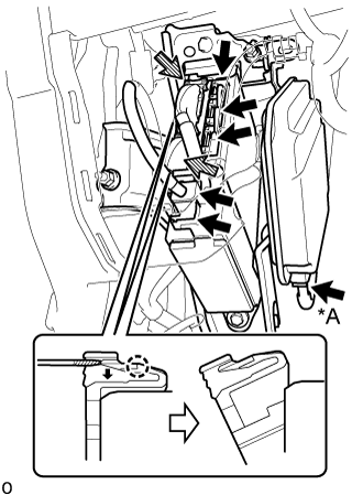
Press the claw of the cowl side junction block LH as shown in the illustration to release the lock.
Text in Illustration *a Claw of Cowl Side Junction Block LH *b Main Body ECU (Multiplex Network Body ECU)
 |
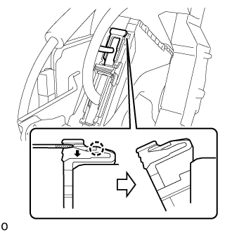
With the cowl side junction block LH lock released, insert a screwdriver with its tip wrapped with protective tape horizontally between the main body ECU (multiplex network body ECU) and cowl side junction block LH.
Text in Illustration Protective Tape - NOTICE:
- Use a screwdriver with a diameter of between 5.0 mm (0.197 in.) and 6.3 mm (0.248 in.) and a length of approximately 90 mm (3.54 in.).
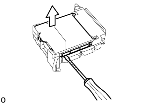 |
Using the screwdriver, carefully raise the main body ECU (multiplex network body ECU) to the position where the connector becomes disengaged.
- NOTICE:
- Do not insert the screwdriver between the cowl side junction block LH and the connector of the main body ECU (multiplex network body ECU).
- Do not twist the screwdriver to raise the main body ECU (multiplex network body ECU).
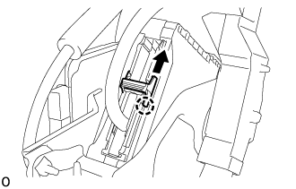
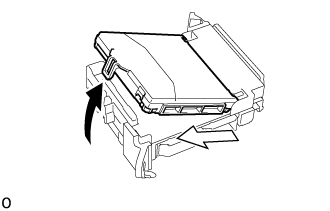
Raise the main body ECU (multiplex network body ECU) as shown by the black arrow, and then slide it out as shown by the white arrow in the illustration.
Text in Illustration Raise 
Slide Out - NOTICE:
- Do not touch the main body ECU (multiplex network body ECU) connector.
 |