Dtc C1Ab3 Short To Gnd In Outer Mirror Indicator(Slave)
DESCRIPTION
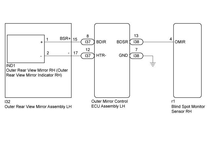
WIRING DIAGRAM
INSPECTION PROCEDURE
CHECK FOR DTC
CHECK HARNESS AND CONNECTOR (BLIND SPOT MONITOR SENSOR RH - OUTER MIRROR CONTROL ECU ASSEMBLY RH)
CHECK HARNESS AND CONNECTOR (OUTER MIRROR CONTROL ECU ASSEMBLY RH - OUTER REAR VIEW MIRROR ASSEMBLY RH)
CHECK OUTER REAR VIEW MIRROR ASSEMBLY RH
INSPECT OUTER MIRROR CONTROL ECU ASSEMBLY RH
REPLACE OUTER REAR VIEW MIRROR RH
DTC C1AB3 Short to GND in Outer Mirror Indicator(Slave) |
DESCRIPTION
This DTC is stored when the blind spot monitor sensor RH detects a ground short in the outer rear view mirror indicator RH.DTC No.
| DTC Detection Condition
| Trouble Area
|
C1AB3
| Both of the following conditions are met:
- The blind spot monitor main switch (steering pad switch assembly [multi-function switch]) is on.
- The current that is sent from the blind spot monitor sensor to the indicator is above a specified level for a specified period of time.
| - Outer rear view mirror RH (outer rear view mirror indicator RH)
- Outer rear view mirror assembly RH
- Harness or connector
- Blind spot monitor sensor RH
- Outer mirror control ECU assembly RH
|
WIRING DIAGRAM
INSPECTION PROCEDURE
- NOTICE:
- When checking for DTCs, make sure that the blind spot monitor main switch (steering pad switch assembly [multi-function switch]) is on.
Clear the DTCs (Click here).
Recheck for DTCs and check if the same DTC is output again.
- OK:
- No DTCs are output.
| 2.CHECK HARNESS AND CONNECTOR (BLIND SPOT MONITOR SENSOR RH - OUTER MIRROR CONTROL ECU ASSEMBLY RH) |
Disconnect the blind spot monitor sensor RH connector.
Disconnect the I38 outer mirror control ECU assembly RH connector.
Measure the resistance according to the value(s) in the table below.
- Standard Resistance:
Tester Connection
| Condition
| Specified Condition
|
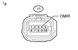
r1-4 (OMIR) - Body ground
| Always
| 10 kΩ or higher
|
Text in Illustration*a
| Front view of wire harness connector
(to Blind Spot Monitor Sensor RH)
|
| | REPAIR OR REPLACE HARNESS OR CONNECTOR |
|
|
| 3.CHECK HARNESS AND CONNECTOR (OUTER MIRROR CONTROL ECU ASSEMBLY RH - OUTER REAR VIEW MIRROR ASSEMBLY RH) |
Disconnect the outer mirror control ECU assembly RH connector.
Disconnect the I32 outer rear view mirror assembly RH connector.
Measure the resistance according to the value(s) in the table below.
- Standard Resistance:
Tester Connection
| Condition
| Specified Condition
|
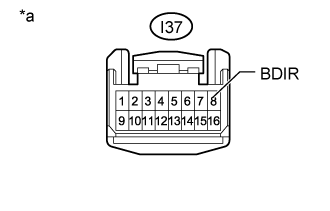
I37-8 (BDIR) - Body ground
| Always
| 10 kΩ or higher
|
Text in Illustration*a
| Front view of wire harness connector
(to Outer Mirror Control ECU Assembly RH)
|
| | REPAIR OR REPLACE HARNESS OR CONNECTOR |
|
|
| 4.CHECK OUTER REAR VIEW MIRROR ASSEMBLY RH |
Disconnect the outer rear view mirror assembly RH connector.
Disconnect the IND1 outer rear view mirror RH connector.
Measure the resistance according to the value(s) in the table below.
- Standard Resistance:
Tester Connection
| Condition
| Specified Condition
|
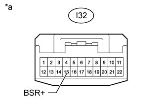
I32-15 (BSR+) - Body ground
| Always
| 10 kΩ or higher
|
Text in Illustration*a
| Front view of wire harness connector
(to Outer Rear View Mirror Assembly RH)
|
| | REPLACE OUTER REAR VIEW MIRROR ASSEMBLY RH (Click here) |
|
|
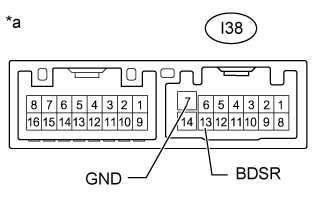
| 5.INSPECT OUTER MIRROR CONTROL ECU ASSEMBLY RH |
Remove the outer mirror control ECU assembly RH connector (Click here).
Measure the resistance according to the value(s) in the table below.
- Standard Resistance:
Tester Connection
| Condition
| Specified Condition
|
I38-13 (BDSR) - I38-7 (GND)
| Always
| 10 kΩ or higher
|
Text in Illustration*a
| Component without harness connected
(Outer Mirror Control ECU Assembly RH)
|
| | REPLACE OUTER MIRROR CONTROL ECU ASSEMBLY RH (Click here) |
|
|
| 6.REPLACE OUTER REAR VIEW MIRROR RH |
Replace the outer rear view mirror RH (Click here).
Clear the DTCs (Click here).
Recheck for DTCs and check if the same DTC is output again.
- OK:
- No DTCs are output.
| OK |
|
|
|
| END (OUTER REAR VIEW MIRROR RH WAS DEFECTIVE) |
|