Audio Visual Telematics. Land Cruiser. Urj200, 202 Grj200 Vdj200
Park Assist Monitoring. Land Cruiser. Urj200, 202 Grj200 Vdj200
Rear View Monitor System -- Terminals Of Ecu |
| CHECK RADIO AND DISPLAY RECEIVER ASSEMBLY |
Disconnect the F120 and F124 radio and display receiver assembly connectors.

Measure the voltage and resistance according to the value(s) in the table below.
Terminal No. (Symbol) Wiring Color Terminal Description Condition Specified Condition F120-3 (ACC1) - Body ground BE - Body ground Power source Engine switch on (ACC) 11 to 14 V Engine switch off Below 1 V F120-4 (+B1) - Body ground V - Body ground Power source Always 11 to 14 V F120-7 (GND1) - Body ground W-B - Body ground Ground Always Below 1 Ω F124-1 (IG) - Body ground B - Body ground Power source Engine switch on (IG) 11 to 14 V Engine switch off Below 1 V Reconnect the F120 and F124 radio and display receiver assembly connectors.
Measure the waveform according to the value(s) in the table below.
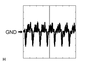
Terminal No. (Symbol) Wiring Color Terminal Description Condition Specified Condition F118-11 (CA+) - F118-23 (CGND) B - Shielded Power source Engine switch on (ACC) 5.5 to 7.05 V F118-12 (V+) - F118-24 (V-) R - W Display signal Engine switch on (IG), shift lever in R Pulse generation (See waveform 1) Engine switch on (IG), shift lever in R, screen blacked out by covering camera lens Pulse generation (See waveform 2) F124-2 (REV) - Body ground L - Body ground Reverse signal Engine switch on (IG), shift lever in R 7.5 to 14 V Engine switch on (IG), shift lever not in R Below 1 V Using an oscilloscope, check waveform 1.
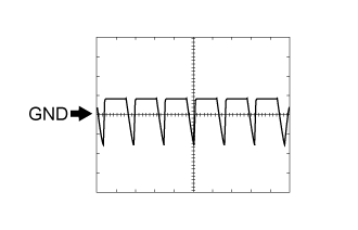
Waveform Item Content Terminal No. (Symbol) F118-12 (V+) - F118-24 (V-) Tool Setting 0.2 V/DIV., 50 μs/DIV. Condition Engine switch on (IG), shift lever in R Using an oscilloscope, check waveform 2.
Waveform Item Content Terminal No. (Symbol) F118-12 (V+) - F118-24 (V-) Tool Setting 0.2 V/DIV., 50 μs/DIV. Condition Engine switch on (IG), shift lever in R and camera lens is covered, blacking out the screen
 |
 |