Navigation System Visual Mute Signal Circuit Between Navigation Ecu And Multi-Display
DESCRIPTION
WIRING DIAGRAM
INSPECTION PROCEDURE
CHECK MULTI-MEDIA MODULE RECEIVER ASSEMBLY
CHECK HARNESS AND CONNECTOR (MULTI-MEDIA MODULE RECEIVER ASSEMBLY - MULTI-DISPLAY ASSEMBLY)
NAVIGATION SYSTEM - Visual Mute Signal Circuit between Navigation ECU and Multi-display |
DESCRIPTION
The multi-media module receiver assembly sends a visual mute signal to the multi-display assembly. As a result, a black screen is inserted when the screen changes so that noise and distorted images are not displayed.When an open exists in the circuit, noise and distorted images will be displayed instead of a black screen.When a short exists in the circuit, even though the multi-display assembly is operating normally, noise and distorted images will be displayed (black screen will not be displayed) during screen changes or the black screen will always be displayed.
WIRING DIAGRAM
INSPECTION PROCEDURE
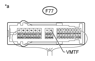
| 1.CHECK MULTI-MEDIA MODULE RECEIVER ASSEMBLY |
Measure the voltage according to the value(s) in the table below.
- Standard Voltage:
Tester Connection
| Condition
| Specified Condition
|
F77-10 (VMTF) - Body ground
| Engine switch on (ACC), screen display changes.
| 3.5 V or higher → Below 1 V → 3.5 V or higher
|
Text in Illustration*a
| Component with harness connected
(Multi-media Module Receiver Assembly)
|
| | REPLACE MULTI-MEDIA MODULE RECEIVER ASSEMBLY (Click here) |
|
|
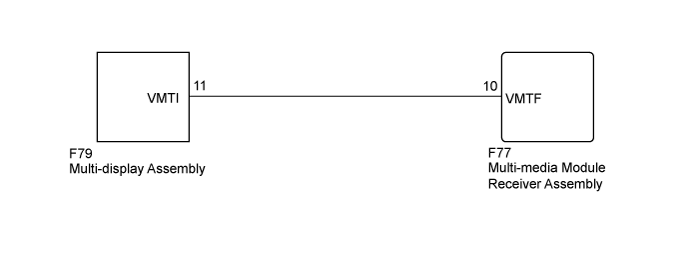
| 2.CHECK HARNESS AND CONNECTOR (MULTI-MEDIA MODULE RECEIVER ASSEMBLY - MULTI-DISPLAY ASSEMBLY) |
Disconnect the F79 multi-display assembly connector.
Disconnect the F77 multi-media module receiver assembly connector.
Measure the resistance according to the value(s) in the table below.
- Standard Resistance:
Tester Connection
| Condition
| Specified Condition
|
F79-11 (VMTI) - F77-10 (VMTF)
| Always
| Below 1 Ω
|
F79-11 (VMTI) - Body ground
| Always
| 10 kΩ or higher
|
| | REPAIR OR REPLACE HARNESS OR CONNECTOR |
|
|
| OK |
|
|
|
| PROCEED TO NEXT SUSPECTED AREA SHOWN IN PROBLEM SYMPTOMS TABLE (Click here) |
|