Navigation System Avc-Lan Circuit
DESCRIPTION
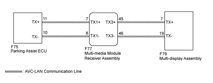
WIRING DIAGRAM
INSPECTION PROCEDURE
INSPECT MULTI-MEDIA MODULE RECEIVER ASSEMBLY
CHECK HARNESS AND CONNECTOR (AVC-LAN CIRCUIT)
INSPECT MALFUNCTIONING PARTS
NAVIGATION SYSTEM - AVC-LAN Circuit |
DESCRIPTION
Each audio system component connected to the AVC-LAN (communication bus) transfers switch signals using the audio visual communication local area network.If a short to +B or short to ground occurs in the AVC-LAN, the audio system will not function normally because communication is not possible.
WIRING DIAGRAM
INSPECTION PROCEDURE
- NOTICE:
- Depending on the parts that are replaced during vehicle inspection or maintenance, performing initialization, registration or calibration may be needed. Refer to Precaution for Navigation System (Click here).
| 1.INSPECT MULTI-MEDIA MODULE RECEIVER ASSEMBLY |
Remove the multi-media module receiver assembly with the connector(s) still connected (Click here).
Measure the resistance according to the value(s) in the table below.
- Standard Resistance:
Tester Connection
| Condition
| Specified Condition
|
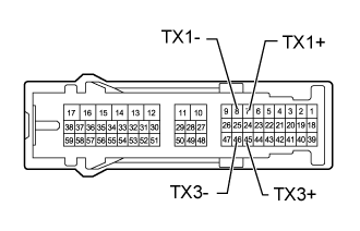
7 (TX1+) - 8 (TX1-)
| Always
| 60 to 80 Ω
|
45 (TX3+) - 46 (TX3-)
| Always
| 60 to 80 Ω
|
| | REPLACE MULTI-MEDIA MODULE RECEIVER ASSEMBLY (Click here) |
|
|
| 2.CHECK HARNESS AND CONNECTOR (AVC-LAN CIRCUIT) |
Disconnect the F77 multi-media module receiver assembly connector.
Disconnect the F79 multi-display assembly connector.
Disconnect the F75 parking assist ECU connector.
Measure the resistance according to the value(s) in the table below.
- Standard Resistance:
Tester Connection
| Condition
| Specified Condition
|
F77-45 (TX3+) - F79-7 (TX+)
| Always
| Below 1 Ω
|
F77-46 (TX3-) - F79-19 (TX-)
| Always
| Below 1 Ω
|
F77-7 (TX1+) - F75-11 (TX+)
| Always
| Below 1 Ω
|
F77-8 (TX1-) - F75-10 (TX- )
| Always
| Below 1 Ω
|
F77-45 (TX3+) - Body ground
| Always
| 10 kΩ or higher
|
F77-46 (TX3-) - Body ground
| Always
| 10 kΩ or higher
|
F77-7 (TX1+) - Body ground
| Always
| 10 kΩ or higher
|
F77-8 (TX1-) - Body ground
| Always
| 10 kΩ or higher
|
| | REPAIR OR REPLACE HARNESS OR CONNECTOR |
|
|
| 3.INSPECT MALFUNCTIONING PARTS |
Disconnect and reconnect each slave unit one by one until the master unit returns to normal operation.
- HINT:
- Check all slave units.
- When disconnecting a slave unit causes the master unit to return to normal operation, this indicates that the slave unit is malfunctioning. Replace the malfunctioning slave unit.
- OK:
- Master unit returns to normal operation.
| | REPLACE MULTI-MEDIA MODULE RECEIVER ASSEMBLY (Click here) |
|
|
| OK |
|
|
|
| REPLACE MALFUNCTIONING PARTS |
|