Navigation System Avc-Lan Circuit
DESCRIPTION
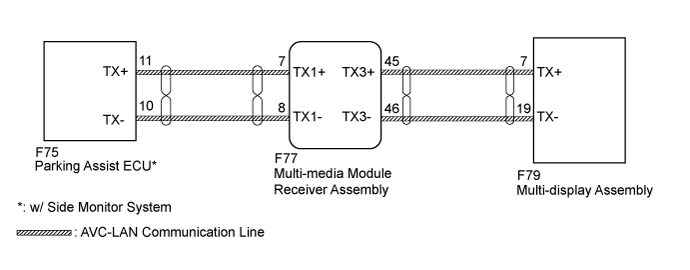
WIRING DIAGRAM
INSPECTION PROCEDURE
INSPECT MULTI-MEDIA MODULE RECEIVER ASSEMBLY
CHECK HARNESS AND CONNECTOR (MULTI-MEDIA MODULE RECEIVER ASSEMBLY - BATTERY AND BODY GROUND)
INSPECT MALFUNCTIONING PARTS
NAVIGATION SYSTEM - AVC-LAN Circuit |
DESCRIPTION
Each audio system component connected to the AVC-LAN (communication bus) transfers switch signals using the audio visual communication local area network.If a short to +B or short to ground occurs in the AVC-LAN, the audio system will not function normally because communication is not possible.
WIRING DIAGRAM
INSPECTION PROCEDURE
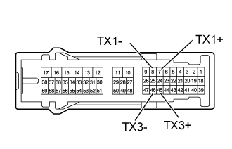
| 1.INSPECT MULTI-MEDIA MODULE RECEIVER ASSEMBLY |
Remove the multi-media module receiver assembly (Click here).
Measure the resistance according to the value(s) in the table below.
- Standard Resistance:
Tester Connection
| Condition
| Specified Condition
|
7 (TX1+) - 8 (TX1-)
| Always
| 60 to 80 Ω
|
45 (TX3+) - 46 (TX3-)
| Always
| 60 to 80 Ω
|
| | REPLACE MULTI-MEDIA MODULE RECEIVER ASSEMBLY (Click here) |
|
|
| 2.CHECK HARNESS AND CONNECTOR (MULTI-MEDIA MODULE RECEIVER ASSEMBLY - BATTERY AND BODY GROUND) |
- HINT:
- For details of the connectors, refer to Terminals of ECU (Click here).
Referring to the following AVC-LAN wiring diagram, check all AVC-LAN circuits.
Disconnect all connectors in all AVC-LAN circuits.
Check for an open or short in all AVC-LAN circuits.
- OK:
- There is no open or short circuit.
| | REPAIR OR REPLACE HARNESS OR CONNECTOR |
|
|
| 3.INSPECT MALFUNCTIONING PARTS |
Disconnect and reconnect each slave unit one by one until the master unit returns to normal operation.
- HINT:
- Check all slave units.
- When disconnecting a slave unit causes the master unit to return to normal operation, this indicates that the slave unit is malfunctioning. Replace the malfunctioning slave unit.
- OK:
- Master unit returns to normal operation.
| | PROCEED TO NEXT SUSPECTED AREA SHOWN IN PROBLEM SYMPTOMS TABLE (Click here) |
|
|
| OK |
|
|
|
| REPLACE MALFUNCTIONING PARTS |
|