Navigation System Steering Pad Switch Circuit
DESCRIPTION
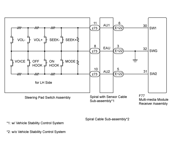
WIRING DIAGRAM
INSPECTION PROCEDURE
INSPECT STEERING PAD SWITCH ASSEMBLY
CONFIRM MODEL
INSPECT SPIRAL WITH SENSOR CABLE SUB-ASSEMBLY
CHECK HARNESS AND CONNECTOR (MULTI-MEDIA MODULE RECEIVER ASSEMBLY - SPIRAL WITH SENSOR CABLE SUB-ASSEMBLY)
INSPECT SPIRAL CABLE SUB-ASSEMBLY
CHECK HARNESS AND CONNECTOR (MULTI-MEDIA MODULE RECEIVER ASSEMBLY - SPIRAL CABLE SUB-ASSEMBLY)
NAVIGATION SYSTEM - Steering Pad Switch Circuit |
DESCRIPTION
This circuit sends an operation signal from the steering pad switch assembly to the multi-media module receiver assembly.If there is an open in the circuit, the audio system cannot be operated using the steering pad switch assembly.If there is a short in the circuit, the same condition as when a switch is continuously depressed occurs.Therefore, the multi-media module receiver assembly cannot be operated using the steering pad switch assembly, and also the multi-media module receiver assembly itself cannot function.
WIRING DIAGRAM
INSPECTION PROCEDURE
- NOTICE:
- The vehicle is equipped with a Supplemental Restraint System (SRS) which includes components such as airbags. Before servicing (including removal or installation of parts), be sure to read the precaution for Supplemental Restraint System (Click here).
| 1.INSPECT STEERING PAD SWITCH ASSEMBLY |
Remove the steering pad switch assembly (Click here).
Inspect the steering pad switch assembly (Click here).
Choose the model to be inspected.
ModelResult
| Proceed to
|
w/ Vehicle Stability Control System
| A
|
w/o Vehicle Stability Control System
| B
|
| 3.INSPECT SPIRAL WITH SENSOR CABLE SUB-ASSEMBLY |
Remove the spiral with sensor cable sub-assembly (Click here).
Inspect the spiral with sensor cable sub-assembly (Click here).
| | REPLACE SPIRAL WITH SENSOR CABLE SUB-ASSEMBLY (Click here) |
|
|
| 4.CHECK HARNESS AND CONNECTOR (MULTI-MEDIA MODULE RECEIVER ASSEMBLY - SPIRAL WITH SENSOR CABLE SUB-ASSEMBLY) |
Disconnect the F77 multi-media module receiver assembly connector.
Disconnect the E122 spiral with sensor cable sub-assembly connector.
Measure the resistance according to the value(s) in the table below.
- Standard Resistance:
Tester Connection
| Switch Condition
| Specified Condition
|
F77-30 (SW1) - E122-6 (AU1)
| Always
| Below 1 Ω
|
F77-31 (SW2) - E122-5 (AU2)
| Always
| Below 1 Ω
|
F77-32 (SWG) - E122-3 (EAU)
| Always
| Below 1 Ω
|
F77-30 (SW1) - Body ground
| Always
| 10 kΩ or higher
|
F77-31 (SW2) - Body ground
| Always
| 10 kΩ or higher
|
| | REPAIR OR REPLACE HARNESS OR CONNECTOR |
|
|
| OK |
|
|
|
| PROCEED TO NEXT SUSPECTED AREA SHOWN IN PROBLEM SYMPTOMS TABLE (Click here) |
|
| 5.INSPECT SPIRAL CABLE SUB-ASSEMBLY |
Remove the spiral cable sub-assembly (Click here).
Inspect the spiral cable sub-assembly (Click here).
| 6.CHECK HARNESS AND CONNECTOR (MULTI-MEDIA MODULE RECEIVER ASSEMBLY - SPIRAL CABLE SUB-ASSEMBLY) |
Disconnect the F77 multi-media module receiver assembly connector.
Disconnect the E122 spiral cable sub-assembly connector.
Measure the resistance according to the value(s) in the table below.
- Standard Resistance:
Tester Connection
| Switch Condition
| Specified Condition
|
F77-30 (SW1) - E122-6 (AU1)
| Always
| Below 1 Ω
|
F77-31 (SW2) - E122-5 (AU2)
| Always
| Below 1 Ω
|
F77-32 (SWG) - E122-3 (EAU)
| Always
| Below 1 Ω
|
F77-30 (SW1) - Body ground
| Always
| 10 kΩ or higher
|
F77-31 (SW2) - Body ground
| Always
| 10 kΩ or higher
|
| | REPAIR OR REPLACE HARNESS OR CONNECTOR |
|
|
| OK |
|
|
|
| PROCEED TO NEXT SUSPECTED AREA SHOWN IN PROBLEM SYMPTOMS TABLE (Click here) |
|