Dtc B15D6 Display Disconnected
DESCRIPTION
WIRING DIAGRAM
INSPECTION PROCEDURE
CLEAR DTC
CHECK DTC
CHECK HARNESS AND CONNECTOR (MULTI-DISPLAY ASSEMBLY - BATTERY AND BODY GROUND)
INSPECT MULTI-MEDIA MODULE RECEIVER ASSEMBLY
CHECK HARNESS AND CONNECTOR (MULTI-MEDIA MODULE RECEIVER ASSEMBLY - MULTI-DISPLAY ASSEMBLY)
REPLACE MULTI-DISPLAY ASSEMBLY
CLEAR DTC
CHECK DTC
DTC B15D6 Display Disconnected |
DESCRIPTION
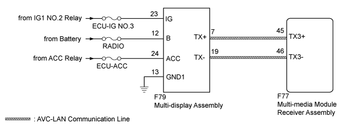
The multi-display assembly and multi-media module receiver assembly are connected by an AVC-LAN communication line.When an AVC-LAN communication error occurs between the multi-media module receiver assembly and multi-display assembly, these DTCs will be stored.DTC Code
| DTC Detection Condition
| Trouble Area
|
B15D6*
| A device that is listed in the AVC-LAN connected device record of the master unit is missing.
| - AVC-LAN circuit
- Multi-display assembly
- Multi-media module receiver assembly
- Harness or connector
|
- HINT:
- *: Even if no fault is present, this DTC may be stored depending on the battery condition or engine start voltage.
- The multi-media module receiver assembly is the master unit.
WIRING DIAGRAM
INSPECTION PROCEDURE
- NOTICE:
- Inspect the fuses for circuits related to this system before performing the following inspection procedure.
- Depending on the parts that are replaced during vehicle inspection or maintenance, performing initialization, registration or calibration may be needed. Refer to Precaution for Navigation System (Click here).
Clear the DTCs (Click here).
Recheck for DTCs and check if the same DTC is output again (Click here).
- OK:
- No DTCs are output.
| 3.CHECK HARNESS AND CONNECTOR (MULTI-DISPLAY ASSEMBLY - BATTERY AND BODY GROUND) |
Disconnect the multi-display assembly connector.
Measure the resistance according to the value(s) in the table below.
- Standard Resistance:
Tester Connection
| Condition
| Specified Condition
|
F79-13 (GND1) - Body ground
| Always
| Below 1 Ω
|
Measure the voltage according to the value(s) in the table below.
- Standard Voltage:
Tester Connection
| Condition
| Specified Condition
|
F79-12 (B) - F79-13 (GND1)
| Always
| 11 to 14 V
|
F79-23 (IG) - F79-13 (GND1)
| Engine switch on (IG)
| 11 to 14 V
|
F79-24 (ACC) - F79-13 (GND1)
| Engine switch on (ACC)
| 11 to 14 V
|
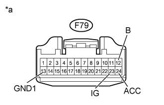
Text in Illustration*a
| Front view of wire harness connector
(to Multi-display Assembly)
|
| | REPAIR OR REPLACE HARNESS OR CONNECTOR |
|
|
| 4.INSPECT MULTI-MEDIA MODULE RECEIVER ASSEMBLY |
Remove the multi-media module receiver assembly (Click here).
Measure the resistance according to the value(s) in the table below.
- Standard Resistance:
Tester Connection
| Condition
| Specified Condition
|
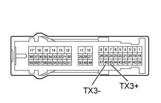
45 (TX3+) - 46 (TX3-)
| Always
| 60 to 80 Ω
|
| | REPLACE MULTI-MEDIA MODULE RECEIVER ASSEMBLY (Click here) |
|
|
| 5.CHECK HARNESS AND CONNECTOR (MULTI-MEDIA MODULE RECEIVER ASSEMBLY - MULTI-DISPLAY ASSEMBLY) |
Disconnect the F77 multi-media module receiver assembly connector.
Disconnect the F79 multi-display assembly connector.
Measure the resistance according to the value(s) in the table below.
- Standard Resistance:
Tester Connection
| Condition
| Specified Condition
|
F77-45 (TX3+) - F79-7 (TX+)
| Always
| Below 1 Ω
|
F77-46 (TX3-) - F79-19 (TX-)
| Always
| Below 1 Ω
|
F77-45 (TX3+) - Body ground
| Always
| 10 kΩ or higher
|
F77-46 (TX3-) - Body ground
| Always
| 10 kΩ or higher
|
| | REPAIR OR REPLACE HARNESS OR CONNECTOR |
|
|
| 6.REPLACE MULTI-DISPLAY ASSEMBLY |
Replace the multi-display assembly with a new or normally functioning one (Click here).
Clear the DTCs (Click here).
Recheck for DTCs and check if the same DTC is output again (Click here).
- OK:
- No DTCs are output.
| | REPLACE MULTI-MEDIA MODULE RECEIVER ASSEMBLY (Click here) |
|
|
| OK |
|
|
|
| END (MULTI-DISPLAY ASSEMBLY IS DEFECTIVE) |
|