Stereo Jack Adapter Assembly -- Removal |
| 1. PRECAUTION |
- NOTICE:
- After turning the ignition switch off, waiting time may be required before disconnecting the cable from the battery terminal. Therefore, make sure to read the disconnecting the cable from the battery terminal notice before proceeding with work (Click here).
| 2. DISCONNECT CABLE FROM NEGATIVE BATTERY TERMINAL |
- NOTICE:
- When disconnecting the cable, some systems need to be initialized after the cable is reconnected (Click here).
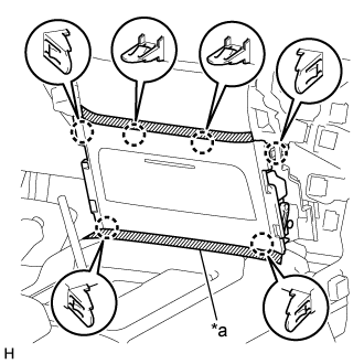
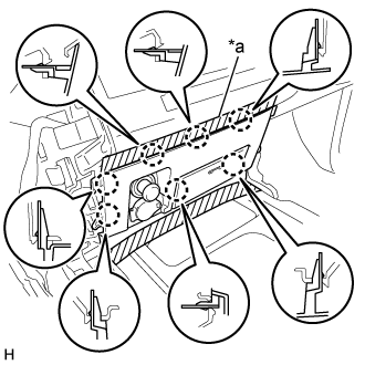
| 3. REMOVE NO. 2 INSTRUMENT PANEL FINISH PANEL CUSHION |
for Type A:
Put protective tape around the No. 2 instrument panel finish panel cushion.
Text in Illustration *a Protective Tape Using a moulding remover B, detach the 4 claws and 3 clips and remove the No. 2 instrument panel finish panel cushion.
for Type B:
Put protective tape around the No. 2 instrument panel finish panel cushion.
Text in Illustration *a Protective Tape Using a moulding remover, detach the 7 claws and remove the No. 2 instrument panel finish panel cushion.
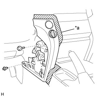
| 4. REMOVE LOWER INSTRUMENT PANEL PAD SUB-ASSEMBLY LH |
for Type A:
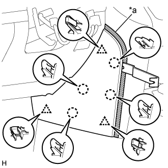
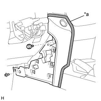
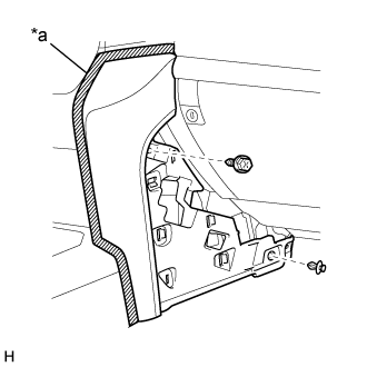
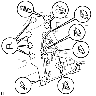
Put protective tape around the lower instrument panel pad sub-assembly LH.
Text in Illustration *a Protective Tape Remove the clip and screw.
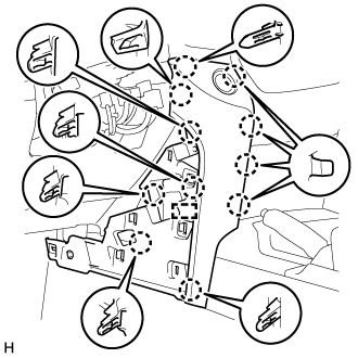
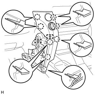
Detach the 11 claws and guide.
Disconnect the connector and detach the clamps and remove the lower instrument panel pad sub-assembly LH.
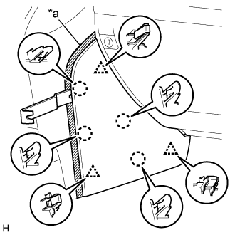
for Type B:
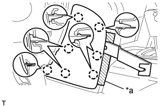
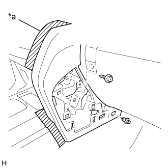
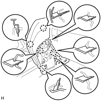
Put protective tape around the lower instrument panel pad sub-assembly LH.
Text in Illustration *a Protective Tape Remove the clip and screw.
Detach the 8 claws and 2 guides and remove the lower instrument panel pad sub-assembly LH.
| 5. REMOVE NO. 1 INSTRUMENT PANEL FINISH PANEL CUSHION |
for Type A:
Put protective tape around the No. 1 instrument panel finish panel cushion.
Text in Illustration *a Protective Tape Using a moulding remover B, detach the 4 claws and 3 clips and remove the No. 2 instrument panel finish panel cushion.
for Type B:
Put protective tape around the No. 1 instrument panel finish panel cushion.
Text in Illustration *a Protective Tape Using a moulding remover, detach the 7 claws and remove the No. 2 instrument panel finish panel cushion.
| 6. REMOVE LOWER INSTRUMENT PANEL PAD SUB-ASSEMBLY RH |
for Type A:
Put protective tape around the lower instrument panel pad sub-assembly RH.
Text in Illustration *a Protective Tape Remove the clip and screw.
Detach the 11 claws and guide and remove the lower instrument panel pad sub-assembly RH.
for Type B:
Put protective tape around the lower instrument panel pad sub-assembly RH.
Text in Illustration *a Protective Tape Remove the clip and screw.
Detach the 7 claws and remove the lower instrument panel pad sub-assembly RH.
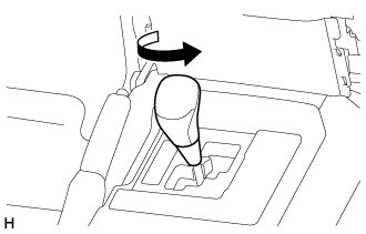
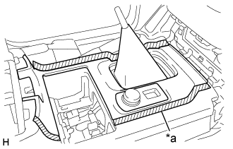
| 7. REMOVE SHIFT LEVER KNOB SUB-ASSEMBLY |
for Type A, for Automatic Transmission:
Twist the shift lever knob sub-assembly in the direction indicated by the arrow and remove it.
for Type A, for Manual Transmission:
Twist the shift lever knob sub-assembly in the direction indicated by the arrow and remove it.
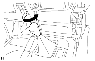
for Type B:
Twist the shift lever knob sub-assembly in the direction indicated by the arrow and remove it.
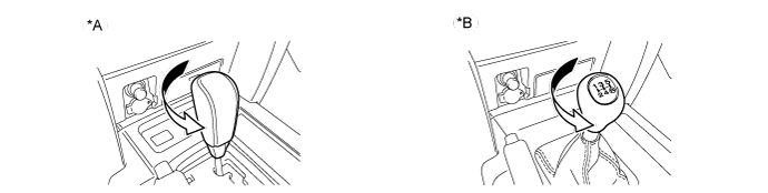
Text in Illustration *A for Automatic Transmission *B for Manual Transmission
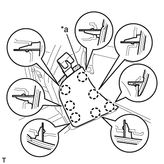
| 8. REMOVE LOWER CENTER INSTRUMENT CLUSTER FINISH PANEL SUB-ASSEMBLY |
for Type A:
Put protective tape around the lower center instrument cluster finish panel sub-assembly.
Text in Illustration *a Protective Tape Detach the 6 claws and remove the lower center instrument cluster finish panel sub-assembly.
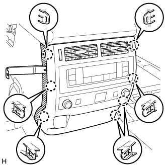
for Type B:
Put protective tape around the lower center instrument cluster finish panel sub-assembly.
Text in Illustration *a Protective Tape Detach the 7 claws.
Disconnect the connectors and remove the lower center instrument cluster finish panel sub-assembly.
| 9. REMOVE CONSOLE CUP HOLDER BOX SUB-ASSEMBLY |
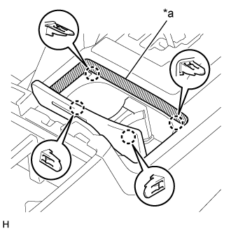 |
Put protective tape around the lower console cup holder box sub-assembly.
Text in Illustration *a Protective Tape
Detach the 4 claws and remove the console cup holder box sub-assembly.
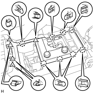
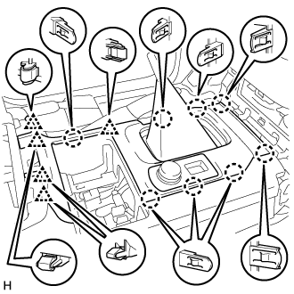
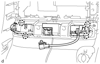
| 10. REMOVE UPPER CONSOLE PANEL |
for Automatic Transmission:
Put protective tape around the upper console panel.
Text in Illustration *a Protective Tape Detach the 8 claws and 5 clips.
Disconnect the connectors and remove the upper console panel.

for Manual Transmission:
Put protective tape around the upper console panel.
Text in Illustration *a Protective Tape Detach the 8 claws and 5 clips.
Disconnect the connectors and remove the upper console panel.
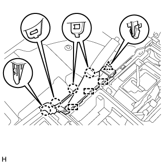
| 11. REMOVE REAR UPPER CONSOLE PANEL SUB-ASSEMBLY |
 |
Put protective tape around the upper rear console panel sub-assembly.
Text in Illustration *a Protective Tape
Detach the 4 claws, clip and 3 guides and remove the upper rear console panel sub-assembly.
 |
| 12. REMOVE UPPER CONSOLE PANEL SUB-ASSEMBLY |
for Type A:
Put protective tape around the upper console panel sub-assembly.
Text in Illustration *a Protective Tape Detach the 8 claws and 4 clips and remove the upper console panel sub-assembly.
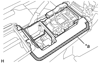
for Type B:
Put protective tape around the upper console panel sub-assembly.
Text in Illustration *a Protective Tape Detach the 14 claws.
Detach the 14 claws. (b) Disconnect the connectors and remove the upper console panel sub-assembly.
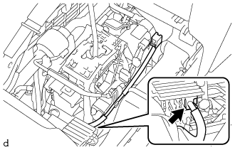
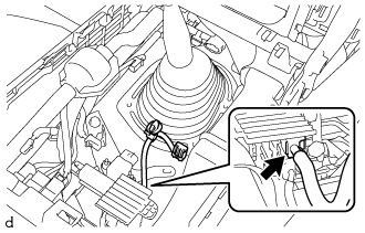
| 13. REMOVE NO. 1 STEREO JACK ADAPTER ASSEMBLY |
for Automatic Transmission:
Detach the 2 claws and remove the stereo jack adapter.
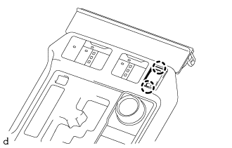 |
for Manual Transmission:
Detach the 2 claws and remove the stereo jack adapter.
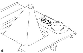
| 14. REMOVE RADIO WIRE |
for Automatic Transmission:
Disconnect the connector and remove the radio wire.
for Manual Transmission:
Disconnect the connector and remove the radio wire.
 |
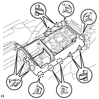
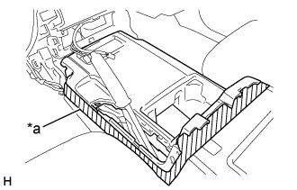
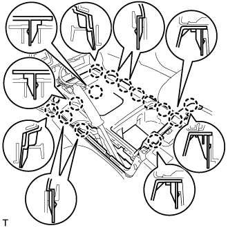
| 15. REMOVE REAR CONSOLE END PANEL SUB-ASSEMBLY |
 |
Put protective tape around the rear console end panel sub-assembly.
Text in Illustration *a Protective Tape
Using a moulding remover B, detach the 7 claws.
Disconnect the connectors and detach the clamps and remove the rear console end panel sub-assembly.
| 16. REMOVE HEADPHONE TERMINAL |
Remove the 2 screws.
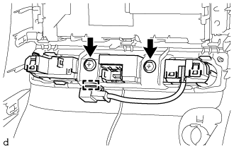 |
Detach the clamp.
Detach the 4 claws and remove the terminal.
 |