Radio Receiver (W/O Multi-Display) -- Removal |
| 1. PRECAUTION |
- NOTICE:
- After turning the ignition switch off, waiting time may be required before disconnecting the cable from the battery terminal. Therefore, make sure to read the disconnecting the cable from the battery terminal notice before proceeding with work (Click here).
| 2. DISCONNECT CABLE FROM NEGATIVE BATTERY TERMINAL |
- NOTICE:
- When disconnecting the cable, some systems need to be initialized after the cable is reconnected (Click here).
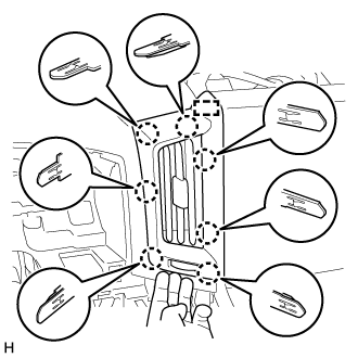
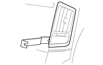
| 3. REMOVE NO. 1 SPEAKER OPENING COVER ASSEMBLY |
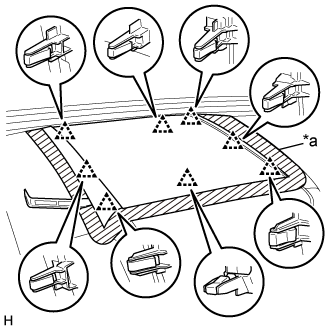 |
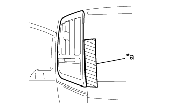
Put protective tape around the No. 1 speaker opening cover assembly.
Text in Illustration *a Protective Tape
Using a moulding remover A, detach the 8 clips and remove the No. 1 speaker opening cover assembly.
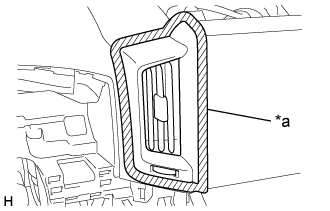
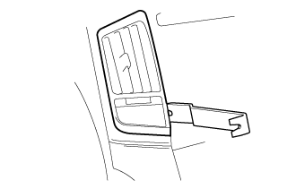
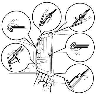
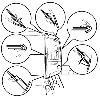
| 4. REMOVE NO. 3 INSTRUMENT PANEL REGISTER ASSEMBLY |
for Type A:
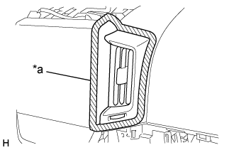
Put protective tape around the No. 3 instrument panel register assembly.
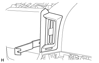
Text in Illustration *a Protective Tape Using moulding remover B, raise the No. 3 instrument panel register assembly.
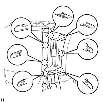
Pull the No. 3 instrument panel register assembly by hand to detach the 7 claws and guide and remove the No. 3 instrument panel register assembly.
for Type B:
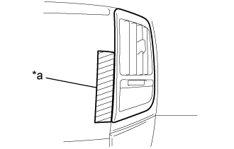
Put protective tape around the No. 3 instrument panel register assembly.
Text in Illustration *a Protective Tape Using moulding remover B, raise the No. 3 instrument panel register assembly.
Pull the No. 3 instrument panel register assembly by hand to detach the 6 claws and remove the No. 3 instrument panel register assembly.
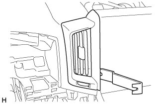
| 5. REMOVE NO. 4 INSTRUMENT PANEL REGISTER ASSEMBLY |
for Type A:
Put protective tape around the No. 3 instrument panel register assembly.
Text in Illustration *a Protective Tape Using moulding remover B, raise the No. 3 instrument panel register assembly.
Pull the No. 3 instrument panel register assembly by hand to detach the 7 claws and guide and remove the No. 3 instrument panel register assembly.
for Type B:
Put protective tape around the No. 3 instrument panel register assembly.
Text in Illustration *a Protective Tape Using moulding remover B, raise the No. 3 instrument panel register assembly.
Pull the No. 3 instrument panel register assembly by hand to detach the 6 claws and remove the No. 3 instrument panel register assembly.
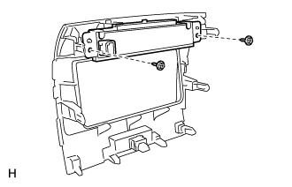
| 6. REMOVE RADIO AND DISPLAY RECEIVER ASSEMBLY WITH BRACKET |
Remove the 2 screws and 2 bolts.
 |
Pull the radio and display receiver assembly with bracket to detach the 6 claws and 2 clips on the backside of the radio and display receiver assembly with bracket.
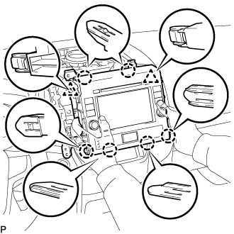 |
Disconnect the connectors and remove the radio and display receiver assembly with bracket.
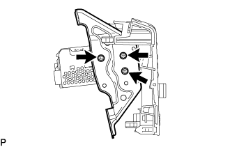
| 7. REMOVE NO. 1 RADIO BRACKET |
Remove the 3 screws and bracket.
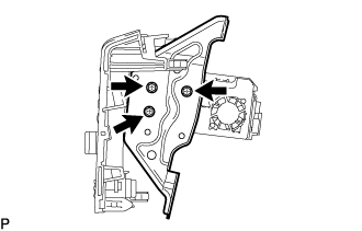 |
| 8. REMOVE NO. 2 RADIO BRACKET |
Remove the 3 screws and bracket.
 |
| 9. REMOVE CLOCK ASSEMBLY |
for Type A:
Remove the 2 screws and clock assembly.
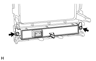
for Type B:
Remove the 2 screws and clock assembly.