Land Cruiser URJ200 URJ202 GRJ200 VDJ200 - 1VD-FTV ENGINE CONTROL
READ OUTPUT DTC (RECORD STORED DTC AND FREEZE FRAME DATA) (PROCEDURE 1)
REPLACE EXHAUST GAS TEMPERATURE SENSOR
REPLACE CATALYTIC CONVERTER (DPF, CCo CATALYTIC CONVERTER)
CHECK AFTER TREATMENT CONTROL SYSTEM
CONFIRM WHETHER MALFUNCTION HAS BEEN SUCCESSFULLY REPAIRED
DTC P200C Diesel Particulate Filter Temperature Too High Bank 1
DTC P200D Diesel Particulate Filter Temperature Too High Bank 2
DTC P200E Catalyst System Temperature Too High Bank 1
DTC P200F Catalyst System Temperature Too High Bank 2
DTC P2428 Exhaust Gas Temperature Too High Bank 1
DTC P2429 Exhaust Gas Temperature Too High Bank 2
DESCRIPTION
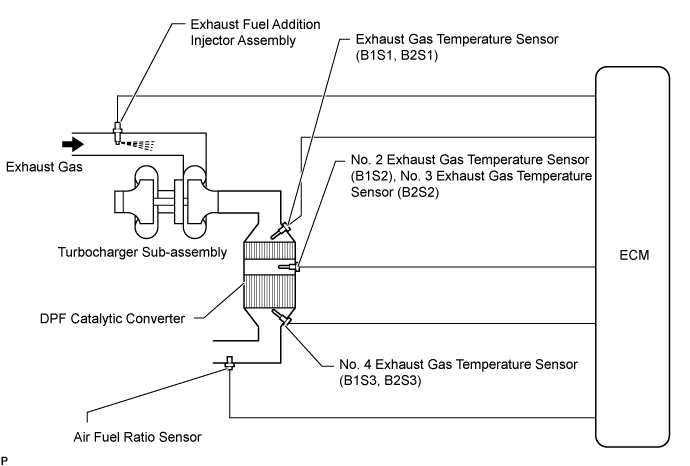
The exhaust fuel addition injector assembly is mounted on the exhaust port of the cylinder head, and low pressure fuel is supplied to the exhaust fuel addition injector assembly by the feed pump in the fuel supply pump assembly. This exhaust fuel addition injector assembly adds fuel in response to a control signal from the ECM, in order to perform PM forced regeneration.
During PM forced regeneration, the exhaust fuel addition injector assembly adds fuel to raise the DPF* catalyst temperature.
- HINT:
- *: Diesel Particulate Filter
| DTC Detection Drive Pattern | DTC Detection Condition | Trouble Area |
| PM forced regeneration* *: When P200C, P200D are detected due to a DPF catalyst problem such as thermal degradation, because the malfunction cannot be duplicated even if the vehicle is driven after PM forced regeneration is performed, perform troubleshooting by following the diagnosis procedure and checking the freeze frame data. | The value of "Exhaust Temperature B1S3, B2S3" is higher than 1000°C (1832°F) for 5 seconds. (1 trip detection logic) | Main Trouble Area Open or short in exhaust fuel addition injector assembly Exhaust fuel addition injector assembly Front exhaust pipe assembly (for bank 1 DPF catalytic converter) Front No. 2 exhaust pipe assembly (for bank 2 DPF catalytic converter) Sub Trouble Area No. 4 exhaust gas temperature sensor (B1S3, B2S3) Air fuel ratio sensor Mass air flow meter Manifold absolute pressure sensor Fuel leaks or blockages in exhaust fuel addition injector assembly Suction control valve (fuel supply pump assembly) Injector assembly Blockages or leaks in air intake system Blockages or leaks in exhaust system Blockages or leaks in EGR system ECM Common Inspection Item: Fuel injection system Intake/exhaust system After treatment control system |
| DTC Detection Drive Pattern | DTC Detection Condition | Trouble Area |
| PM forced regeneration* *: When P200E, P200F are detected due to a DPF catalyst problem such as thermal degradation, because the malfunction cannot be duplicated even if the vehicle is driven after PM forced regeneration is performed, perform troubleshooting by following the diagnosis procedure and checking the freeze frame data. | The value of "Exhaust Temperature B1S2, B2S2" is higher than 1000°C (1832°F) for 5 seconds. (1 trip detection logic) | Main Trouble Area Open or short in exhaust fuel addition injector assembly Exhaust fuel addition injector assembly Front exhaust pipe assembly (for bank 1 DPF catalytic converter) Front No. 2 exhaust pipe assembly (for bank 2 DPF catalytic converter) Monolithic converter assembly RH (for bank 1 CCo catalytic converter) Monolithic converter assembly LH (for bank 2 CCo catalytic converter) Sub Trouble Area No. 2 exhaust gas temperature sensor (B1S2) No. 3 exhaust gas temperature sensor (B2S2) Air fuel ratio sensor Mass air flow meter Manifold absolute pressure sensor Fuel leaks or blockages in exhaust fuel addition injector assembly Suction control valve (fuel supply pump assembly) Injector assembly Blockages or leaks in air intake system Blockages or leaks in exhaust system Blockages or leaks in EGR system ECM Common Inspection Item: Fuel injection system Intake/exhaust system After treatment control system |
| DTC Detection Drive Pattern | DTC Detection Condition | Trouble Area |
| PM forced regeneration* *: When P2428, P2429 are detected due to a DPF catalyst problem such as thermal degradation, because the malfunction cannot be duplicated even if the vehicle is driven after PM forced regeneration is performed, perform troubleshooting by following the diagnosis procedure and checking the freeze frame data. | The value of "Exhaust Temperature B1S1, B2S1" is higher than 1000°C (1832°F) for 5 seconds. (1 trip detection logic) | Main Trouble Area Open or short in exhaust fuel addition injector assembly Exhaust fuel addition injector assembly Monolithic converter assembly RH (for bank 1 CCo catalytic converter) Monolithic converter assembly LH (for bank 2 CCo catalytic converter) Sub Trouble Area Exhaust gas temperature sensor (B1S1, B2S1) Air fuel ratio sensor Mass air flow meter Manifold absolute pressure sensor Fuel leaks or blockages in exhaust fuel addition injector assembly Suction control valve (fuel supply pump assembly) Injector assembly Blockages or leaks in air intake system Blockages or leaks in exhaust system Blockages or leaks in EGR system ECM Common Inspection Item: Fuel injection system Intake/exhaust system After treatment control system |
- HINT:
This DTC or P20CF, P20D5, P244B, P2465, P244C, P244E and P2463 may be stored due to the fact that PM forced regeneration is prohibited due to the fail-safe operation of other DTCs.
| DTC No. | Data List |
| P200C P200D P200E P200F P2428 P2429 | MAF MAP Intake Air Temp (Turbo) Target Booster Pressure Atmosphere Pressure Coolant Temp Engine Speed AFS Voltage B1S1 AFS Voltage B2S1 AF Lambda B1S1 AF Lambda B2S1 Exhaust Fuel Addition FB Exhaust Temperature B1S1 Exhaust Temperature B2S1 Exhaust Temperature B1S2 Exhaust Temperature B2S2 Exhaust Temperature B1S3 Exhaust Temperature B2S3 Catalyst Differential Press Catalyst Differential Press #2 Injection Feedback Val #1 to #8 Injection Volume |
MONITOR DESCRIPTION
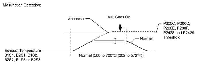
The ECM monitors DPF catalyst converter temperature. When the temperature becomes high due to uncombusted fuel, engine oil or thermal degradation of the DPF catalyst converter, the ECM illuminates the MIL.
INSPECTION PROCEDURE
- NOTICE:
- HINT:
- Read freeze frame data using the GTS. Freeze frame data records the engine condition when malfunctions are detected. When troubleshooting, freeze frame data can help determine if the vehicle was moving or stationary, if the engine was warmed up or not, and other data from the time the malfunction occurred.
| 1.READ OUTPUT DTC (RECORD STORED DTC AND FREEZE FRAME DATA) (PROCEDURE 1) |
Connect the GTS to the DLC3.
Turn the engine switch on (IG) and turn the GTS on.
Enter the following menus: Engine and ECT / Trouble Codes.
Record the stored DTC and freeze frame data.
| NEXT | |
| 2.REPLACE EXHAUST GAS TEMPERATURE SENSOR |
Confirm "Exhaust Temperature B1S1", "Exhaust Temperature B1S2", "Exhaust Temperature B1S3", "Exhaust Temperature B2S1", "Exhaust Temperature B2S2" or "Exhaust Temperature B2S3" in the freeze frame data which was recorded in procedure 1 and determine which exhaust gas temperature sensor to replace.
| Result | Items to be Replaced |
| DTC P2428 is output and the value of "Exhaust Temperature B1S1" is 850°C (1562°F) or higher | Exhaust gas temperature sensor (B1S1) |
| DTC P2429 is output and the value of "Exhaust Temperature B2S1" is 850°C (1562°F) or higher | Exhaust gas temperature sensor (B2S1) |
| DTC P200E is output and the value of "Exhaust Temperature B1S2" is 850°C (1562°F) or higher | No. 2 exhaust gas temperature sensor (B1S2) |
| DTC P200F is output and the value of "Exhaust Temperature B2S2" is 850°C (1562°F) or higher | No. 3 exhaust gas temperature sensor (B2S2) |
| DTC P200C is output and the value of "Exhaust Temperature B1S3" is 850°C (1562°F) or higher | No. 4 exhaust gas temperature sensor (B1S3) |
| DTC P200D is output and the value of "Exhaust Temperature B2S3" is 850°C (1562°F) or higher | No. 4 exhaust gas temperature sensor (B2S3) |
If DTC P200C, P200D, P200E, P200F, P2428 or P2429 is output, the exhaust gas temperature sensors need to be replaced. However, make sure to perform all diagnostic procedures for P200C, P200D, P200E, P200F, P2428 or P2429 before replacing the exhaust gas temperature sensors.
- HINT:
- If the exhaust gas temperature sensors are subjected to an abnormally high temperature, the internal resistance of the sensor increases. This causes incorrect temperature measurement.
| NEXT | |
| 3.CHECK FOR BLACK SMOKE |
Start the engine and drive the vehicle until the engine coolant temperature reaches 60°C (140°F) or higher.
Stop the vehicle and allow the engine to idle.
Fully depress the accelerator pedal for 5 seconds, and then release it [A].
Repeat the above procedure [A] 10 times [B].
Check for black smoke emission during procedure [A] and [B].
- OK:
- Black smoke is emitted less than 5 times.
- HINT:
- Even if the black smoke is very thin, count the number of black smoke emissions if there is any visible smoke.
|
| ||||
|
| ||||
| 4.REPLACE CATALYTIC CONVERTER (DPF, CCo CATALYTIC CONVERTER) |
Determine the parts to replace according to the DTCs output in procedure 1.
| Result | Items to be Replaced |
| P2428 is output | Monolithic converter assembly RH (for bank 1 CCo catalytic converter) |
| P2429 is output | Monolithic converter assembly LH (for bank 2 CCo catalytic converter) |
| P200E is output | Monolithic converter assembly RH (for bank 1 CCo catalytic converter) Front exhaust pipe assembly (for bank 1 DPF catalytic converter) Front No. 2 exhaust pipe assembly (for bank 2 DPF catalytic converter) |
| P200F is output | Monolithic converter assembly LH (for bank 2 CCo catalytic converter) Front exhaust pipe assembly (for bank 1 DPF catalytic converter) Front No. 2 exhaust pipe assembly (for bank 2 DPF catalytic converter) |
| P200C is output | Front exhaust pipe assembly (for bank 1 DPF catalytic converter) Front No. 2 exhaust pipe assembly (for bank 2 DPF catalytic converter) |
| P200D is output | Front exhaust pipe assembly (for bank 1 DPF catalytic converter) Front No. 2 exhaust pipe assembly (for bank 2 DPF catalytic converter) |
- HINT:
- Replace the DPF catalytic converter for bank 1 and bank 2 at the same time.
Even though it has been determined that the exhaust pipe assemblies (DPF catalytic converter) (for bank 1 or bank 2) needs to be replaced, make sure to perform all diagnostic procedures for P200C, P200D, P200E, P200F, P2428 or P2429 before replacing it.
- HINT:
- This DTC is stored because an excessive amount of PM has accumulated and resulted in abnormal combustion. It is necessary to diagnose the cause of abnormal PM accumulation and repair the problem. Therefore, do not perform replacement at this time.
| NEXT | |
| 5.CHECK FUEL INJECTION SYSTEM |
Check the fuel injection system ().
| NEXT | |
| 6.CHECK INTAKE / EXHAUST SYSTEM |
Check the Intake/exhaust system ().
| NEXT | |
| 7.CHECK AFTER TREATMENT CONTROL SYSTEM |
Check the after treatment control system ().
| NEXT | |
| 8.REPLACE MALFUNCTIONING PARTS |
- NOTICE:
- Replace the following items only when it has been determined necessary based on diagnosis for P200C, P200D, P200E, P200F, P2428 or P2429.
Replace the exhaust gas temperature sensor (B1S1) ().
Replace the exhaust gas temperature sensor (B2S1) ().
Replace the No. 2 exhaust gas temperature sensor (B1S2) ().
Replace the No. 3 exhaust gas temperature sensor (B2S2) ().
Replace the No. 4 exhaust gas temperature sensor (B1S3) ().
Replace the No. 4 exhaust gas temperature sensor (B2S3) ().
Replace the exhaust pipe assembly (for bank 1 DPF catalytic converter) ().
Replace the front No. 2 exhaust pipe assembly (for bank 2 DPF catalytic converter) ().
Replace the monolithic converter assembly RH (for bank 1 CCo catalytic converter) ().
Replace the monolithic converter assembly LH (for bank 2 CCo catalytic converter) ().
| NEXT | |
| 9.CATALYST RECORD CLEAR |
Perform the catalyst record clear ().
- HINT:
| NEXT | |
| 10.CONFIRM WHETHER MALFUNCTION HAS BEEN SUCCESSFULLY REPAIRED |
Connect the GTS to the DLC3.
Turn the engine switch on (IG) and turn the GTS on.
Clear the DTCs ().
Perform PM forced regeneration ().
| NEXT | ||
| ||