Audio And Visual System (For Radio And Display Type) Display Signal Circuit Between Radio Receiver And Stereo Jack Adapter
DESCRIPTION
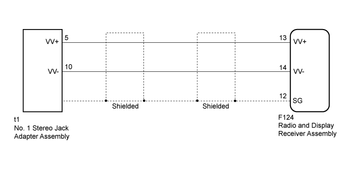
WIRING DIAGRAM
INSPECTION PROCEDURE
CHECK HARNESS AND CONNECTOR (RADIO AND DISPLAY RECEIVER ASSEMBLY - NO. 1 STEREO JACK ADAPTER ASSEMBLY)
AUDIO AND VISUAL SYSTEM (for Radio and Display Type) - Display Signal Circuit between Radio Receiver and Stereo Jack Adapter |
DESCRIPTION
The No. 1 stereo jack adapter assembly sends the display data signal of an external device to the radio and display receiver assembly through this circuit.
WIRING DIAGRAM
INSPECTION PROCEDURE
| 1.CHECK HARNESS AND CONNECTOR (RADIO AND DISPLAY RECEIVER ASSEMBLY - NO. 1 STEREO JACK ADAPTER ASSEMBLY) |
Disconnect the F124 radio and display receiver assembly connector.
Disconnect the t1 No. 1 stereo jack adapter assembly connector.
Measure the resistance according to the value(s) in the table below.
- Standard Resistance:
Tester Connection
| Condition
| Specified Condition
|
F124-13 (VV+) - t1-5 (VV+)
| Always
| Below 1 Ω
|
F124-14 (VV-) - t1-10 (VV-)
| Always
| Below 1 Ω
|
F124-13 (VV+) - Body ground
| Always
| 10 kΩ or higher
|
F124-14 (VV-) - Body ground
| Always
| 10 kΩ or higher
|
F124-12 (SG) - Body ground
| Always
| 10 kΩ or higher
|
| | REPAIR OR REPLACE HARNESS OR CONNECTOR |
|
|
| OK |
|
|
|
| PROCEED TO NEXT SUSPECTED AREA SHOWN IN PROBLEM SYMPTOMS TABLE (Click here) |
|