Steering. Land Cruiser. Urj200, 202 Grj200 Vdj200
Steering Column. Land Cruiser. Urj200, 202 Grj200 Vdj200
Steering Wheel -- Inspection |
- CAUTION:
- The vehicle is equipped with an SRS (Supplemental Restraint System) which includes components such as airbags. Before servicing (including removal or installation of parts), be sure to read the PRECAUTION in the SRS (Click here).
| 1. INSPECT STEERING PAD SWITCH ASSEMBLY |
Measure the resistance according to the value(s) in the table below.
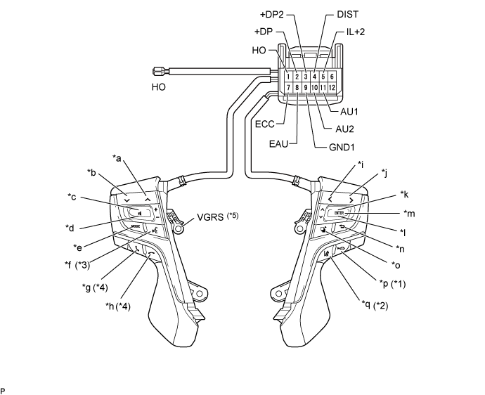
Text in Illustration *1 with ACC switch *2 with LDA switch *3 with Voice switch *4 w/ Hook Switch *5 with VGRS - - *a Seek+ Switch *b Seek- Switch *c Volume+ Switch *d Volume- Switch *e MODE Switch *f Voice Switch *g Off Hook Switch *h On Hook Switch *i LEFT *j RIGHT *k UP *l DOWN *m ENTER *n BACK *o TOP *p ACC *q LDA - - - Standard Resistance:
Tester Connection Switch Condition Specified Condition 11 (AU1) - 8 (EAU) No switch is pushed 95 to 105 kΩ Seek+ switch pushed Below 2.5 Ω Seek- switch pushed 313 to 345 Ω Volume+ switch pushed 950 to 1050 Ω Volume- switch pushed 2955 to 3265 Ω 10 (AU2) - 8 (EAU) No switch is pushed 95 to 105 kΩ Mode switch pushed Below 2.5 Ω Voice switch pushed 2955 to 3265 Ω On Hook switch pushed 313 to 345 Ω Off Hook switch pushed 950 to 1050 Ω 2 (+DP) - 8 (EAU) No switch is pushed 95 to 105 kΩ Left switch pushed Below 2.5 Ω Right switch pushed 2955 to 3265 Ω Up switch pushed 313 to 345 Ω Down switch pushed 950 to 1050 Ω 4 (DIST) - 7 (ECC) No switch is pushed 1MΩ or higher ACC switch pushed Below 2.5 Ω LDA switch pushed 228 to 252 Ω HO - 1 (HO) Always Below 2.5 Ω VGRS - 9 (GND1) Always Below 2.5 Ω
Connect the battery positive (+) lead to terminal 5 (IL+2) and the negative (-) lead to terminal 8 (EAU) of the steering pad switch connector.
Check that the switch illumination comes on.
- OK:
- Steering pad switch illumination comes on.
| 2. INSPECT STEERING PAD SWITCH LH |
Measure the resistance according to the value(s) in the table below.
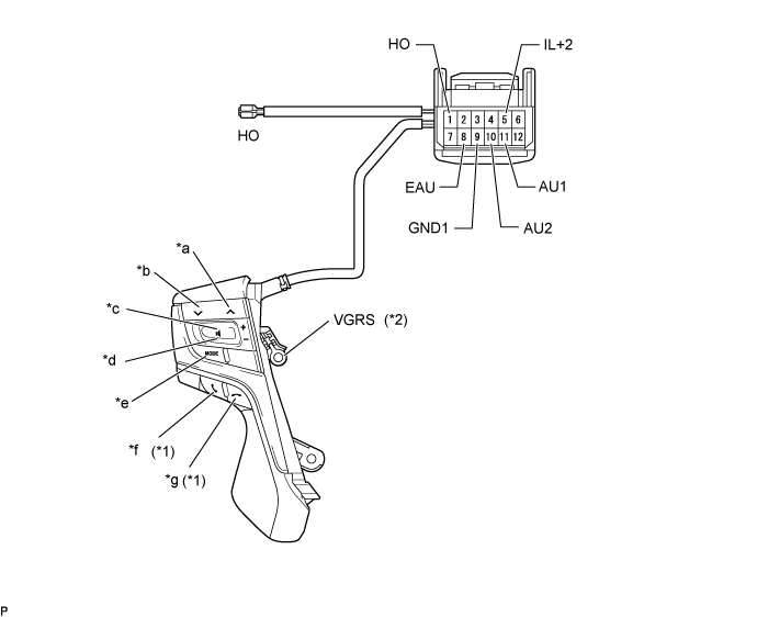
Text in Illustration *1 with Hook Switch *2 with VGRS *a Seek+ Switch *b Seek- Switch *c Volume+ Switch *d Volume- Switch *e MODE Switch *f Off Hook Switch *g On Hook Switch - - - Standard Resistance:
Tester Connection Switch Condition Specified Condition 11 (AU1) - 8 (EAU) No switch is pushed 95 to 105 kΩ Seek+ switch pushed Below 2.5 Ω Seek- switch pushed 313 to 345 Ω Volume+ switch pushed 950 to 1050 Ω Volume- switch pushed 2955 to 3265 Ω 10 (AU2) - 8 (EAU) No switch is pushed 95 to 105 kΩ Mode switch pushed Below 2.5 Ω On Hook switch pushed 313 to 345 Ω Off Hook switch pushed 950 to 1050 Ω HO - 1 (HO) Always Below 2.5 Ω VGRS - 9 (GND1) Always Below 2.5 Ω
Connect the battery positive (+) lead to terminal 5 (IL+2) and the negative (-) lead to terminal 8 (EAU) of the steering pad switch assembly connector.
Check that the switch illumination comes on.
- OK:
- Steering pad switch illumination comes on.