Heated Steering Wheel System Steering Wheel Does Not Heat Up When Heated Steering Wheel Switch Is Pressed
Steering. Land Cruiser. Urj200, 202 Grj200 Vdj200
DESCRIPTION
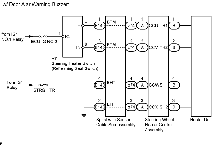
WIRING DIAGRAM
INSPECTION PROCEDURE
INSPECT STEERING WHEEL ASSEMBLY (THERMISTOR·HEATER·THERMOSTAT)
INSPECT SPIRAL WITH SENSOR CABLE SUB-ASSEMBLY
INSPECT REFRESHING SEAT SWITCH (STEERING HEATER SWITCH)
CHECK HARNESS AND CONNECTOR (STEERING HEATER SWITCH - SPIRAL WITH SENSOR CABLE SUB-ASSEMBLY)
CHECK HARNESS AND CONNECTOR (IG CIRCUIT)
CHECK HARNESS AND CONNECTOR (IG CIRCUIT)
CHECK HARNESS AND CONNECTOR (SPIRAL WITH SENSOR CABLE SUB-ASSEMBLY BODY GROUND)
HEATED STEERING WHEEL SYSTEM - Steering Wheel does not Heat Up When Heated Steering Wheel Switch is Pressed |
DESCRIPTION
(Click here)
WIRING DIAGRAM
INSPECTION PROCEDURE
- HINT:
- Inspect the fuses for circuits related to this system before performing the following inspection procedure.
- The steering heater unit is built into the steering wheel assembly which cannot be disassembled. Therefore, when the steering heater unit has a malfunction, replace the steering wheel assembly.
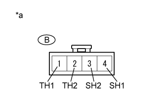
| 1.INSPECT STEERING WHEEL ASSEMBLY (THERMISTOR·HEATER·THERMOSTAT) |
Disconnect the B steering wheel heater control connector.
Measure the resistance according to the value(s) in the table below.
- Standard Resistance:
Tester Connection
| Condition
| Specified Condition
|
B-1 (TH1) - B-2 (TH2)
| 10 to 30°C (50 to 86°F)
| 8.132 to 18.43 kΩ
|
B-4 (SH1) - B-3 (SH2)
| 20°C (68°F)
| 1.89 to 2.25 Ω
|
Text in Illustration*a
| Component without harness connected
(Steering Wheel Assembly)
|
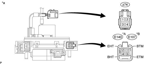
| 2.INSPECT SPIRAL WITH SENSOR CABLE SUB-ASSEMBLY |
Check the connectors and cables of the spiral with sensor cable sub-assembly.
- OK:
- There are no defects such as scratches, cracks, dents or damage on the connectors or cables.
Disconnect the E140*1 or E107*2 and z74 spiral with sensor cable sub-assembly connectors.
- *1: w/ Door Ajar Warning Buzzer
- *2: w/o Door Ajar Warning Buzzer
Text in Illustration*A
| w/ Door Ajar Warning Buzzer
| *B
| w/o Door Ajar Warning Buzzer
|
*a
| Component without harness connected
(Spiral with Sensor Cable Sub-assembly)
| -
| -
|
Measure the resistance according to the value(s) in the table below.
- Standard Resistance:
w/ Door Ajar Warning BuzzerTester Connection
| Condition
| Specified Condition
|
z74-1 - E140-1 (BTM)
| Always
| Below 1 Ω
|
z74-2 - E140-3 (ETM)
| Always
| Below 1 Ω
|
z74-3 - E140-2 (EHT)
| Always
| Below 1 Ω
|
z74-4 - E140-4 (BHT)
| Always
| Below 1 Ω
|
w/o Door Ajar Warning BuzzerTester Connection
| Condition
| Specified Condition
|
z74-1 - E107-1 (BTM)
| Always
| Below 1 Ω
|
z74-2 - E107-3 (ETM)
| Always
| Below 1 Ω
|
z74-3 - E107-2 (EHT)
| Always
| Below 1 Ω
|
z74-4 - E107-4 (BHT)
| Always
| Below 1 Ω
|
| | REPLACE SPIRAL WITH SENSOR CABLE SUB-ASSEMBLY (Click here) |
|
|
| 3.INSPECT REFRESHING SEAT SWITCH (STEERING HEATER SWITCH) |
Remove the steering heater switch (Click here).
Inspect the steering heater switch (Click here).
| 4.CHECK HARNESS AND CONNECTOR (STEERING HEATER SWITCH - SPIRAL WITH SENSOR CABLE SUB-ASSEMBLY) |
Disconnect the V7 steering heater switch connector.
Disconnect the E140*1 or E107*2 spiral with sensor cable sub-assembly connector.
- *1: w/ Door Ajar Warning Buzzer
- *2: w/o Door Ajar Warning Buzzer
Measure the resistance according to the value(s) in the table below.
- Standard Resistance:
w/ Door Ajar Warning BuzzerTester Connection
| Condition
| Specified Condition
|
V7-4 (+) - E140-1 (BTM)
| Always
| Below 1 Ω
|
V7-8 (IN) - E140-3 (ETM)
| Always
| Below 1 Ω
|
w/o Door Ajar Warning BuzzerTester Connection
| Condition
| Specified Condition
|
V7-4 (+) - E107-1 (BTM)
| Always
| Below 1 Ω
|
V7-8 (IN) - E107-3 (ETM)
| Always
| Below 1 Ω
|
| | REPAIR OR REPLACE HARNESS OR CONNECTOR |
|
|
| 5.CHECK HARNESS AND CONNECTOR (IG CIRCUIT) |
Disconnect the V7 steering heater switch connector.
Measure the voltage according to the value(s) in the table below.
- Standard Voltage:
Tester Connection
| Switch Condition
| Specified Condition
|
V7-1 (IG) - Body ground
| Ignition switch ON
| 11 to 14 V
|
| | REPAIR OR REPLACE HARNESS OR CONNECTOR |
|
|
| 6.CHECK HARNESS AND CONNECTOR (IG CIRCUIT) |
Disconnect the E140*1 or E107*2 spiral with sensor cable subassembly connector.
- *1: w/ Door Ajar Warning Buzzer
- *2: w/o Door Ajar Warning Buzzer
Measure the voltage according to the value(s) in the table below.
- Standard Voltage:
w/ Door Ajar Warning BuzzerTester Connection
| Switch Condition
| Specified Condition
|
E140-4 (BHT) - Body ground
| Ignition switch ON
| 11 to 14 V
|
w/o Door Ajar Warning BuzzerTester Connection
| Switch Condition
| Specified Condition
|
E107-4 (BHT) - Body ground
| Ignition switch ON
| 11 to 14 V
|
| | REPAIR OR REPLACE HARNESS OR CONNECTOR |
|
|
| 7.CHECK HARNESS AND CONNECTOR (SPIRAL WITH SENSOR CABLE SUB-ASSEMBLY BODY GROUND) |
Disconnect the E140*1 or E107*2 spiral with sensor cable sub-assembly connector.
- *1: w/ Door Ajar Warning Buzzer
- *2: w/o Door Ajar Warning Buzzer
Measure the resistance according to the value(s) in the table below.
- Standard Resistance:
w/ Door Ajar Warning BuzzerTester Connection
| Condition
| Specified Condition
|
E140-2 (EHT) - Body ground
| Always
| Below 1 Ω
|
w/o Door Ajar Warning BuzzerTester Connection
| Condition
| Specified Condition
|
E107-2 (EHT) - Body ground
| Always
| Below 1 Ω
|
| | REPAIR OR REPLACE HARNESS OR CONNECTOR |
|
|