Dtc C1595/55 Lost Communication With Steering Angle Sensor Module
Steering. Land Cruiser. Urj200, 202 Grj200 Vdj200
DESCRIPTION
WIRING DIAGRAM
INSPECTION PROCEDURE
CHECK DTC
CHECK HARNESS AND CONNECTOR (
VGRS ECU (STEERING CONTROL ECU) - STEERING SENSOR)
CHECK STEERING SENSOR
DTC C1595/55 Lost Communication with Steering Angle Sensor Module |
DTC C15C4/68 Steering Angle Signal (Test Mode DTC) |
DESCRIPTION
Signal transmission between the VGRS ECU (steering control ECU) and steering sensor is performed via serial communication.If a serial communication error occurs between the VGRS ECU (steering control ECU) and steering sensor, the ECU stores DTC C1595/55.The test mode DTC C15C4/68 is only stored during test mode.DTC No.
| DTC Detection Condition
| Trouble Area
|
C1595/55
| With the engine switch on (IG) and a power source voltage of 10 V or more, serial communication from the steering sensor is interrupted for 3 seconds or more.
| - Steering sensor
- VGRS ECU (steering control ECU)
- Harness or connector
|
C15C4/68
| The system enters test mode.
| - Steering sensor
- VGRS ECU (steering control ECU)
- Harness or connector
|
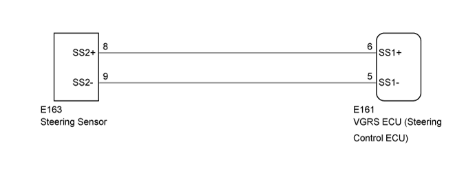
WIRING DIAGRAM
INSPECTION PROCEDURE
- NOTICE:
- When replacing the VGRS ECU (steering control ECU), perform actuator angle neutral point calibration and initialization after replacement (Click here).
Check for DTCs (Click here).
ResultResult
| Proceed to
|
DTCs C15C1/74, C15C2/74 and U0126/56 are not output
| A
|
DTCs C15C1/74, C15C2/74 and U0126/56 are output
| B
|
| | REPAIR CIRCUITS INDICATED BY OUTPUT DTCS (Click here) |
|
|
| 2.CHECK HARNESS AND CONNECTOR (
VGRS ECU (STEERING CONTROL ECU) - STEERING SENSOR) |
Turn the engine switch off.
Disconnect the E161 VGRS ECU (steering control ECU) connector.
Disconnect the E163 steering sensor connector.
Measure the resistance according to the value(s) in the table below.
- Standard Resistance:
Tester Connection
| Condition
| Specified Condition
|
E161-5 (SS1-) - E163-9 (SS2-)
| Always
| Below 1 Ω
|
E161-6 (SS1+) - E163-8 (SS2+)
| Always
| Below 1 Ω
|
E161-5 (SS1-) or E163-9 (SS2-) - Body ground
| Always
| 100 kΩ or higher
|
E161-6 (SS1+) or E163-8 (SS2+) - Body ground
| Always
| 100 kΩ or higher
|
E161-5 (SS1-) - E161-6 (SS1+)
| Always
| 1000 kΩ or higher
|
| | REPAIR OR REPLACE HARNESS OR CONNECTOR |
|
|
Reconnect the E161 VGRS ECU (steering control ECU) connector.
Reconnect the E163 steering sensor connector.
Start the engine.
Measure the voltage according to the value(s) in the table below.
- HINT:
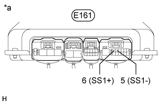
- With the connector connected to the VGRS ECU (steering control ECU), measure the voltage from the rear of the connector.
- Standard Voltage:
Tester Connection
| Condition
| Specified Condition
|
E161-5 (SS1-) - E161-6 (SS1+)
| Steering wheel rotated slowly
| Pulse waveform that alternates between 0 and 5 V is output
|
Text in Illustration*a
| Component with harness connected
(VGRS ECU [Steering Control ECU])
|
ResultResult
| Proceed to
|
OK (for LHD)
| A
|
OK (for RHD)
| B
|
NG
| C
|
| | REPLACE VGRS ECU (STEERING CONTROL ECU) (Click here) |
|
|
| |
|
| A |
|
|
|
| REPLACE VGRS ECU (STEERING CONTROL ECU) (Click here) |
|