DISCONNECT POWER STEERING OIL PRESSURE SENSOR CONNECTOR (w/o Variable Flow Control Solenoid Valve)
DISCONNECT PRESSURE FEED TUBE (w/o Variable Flow Control Solenoid Valve)
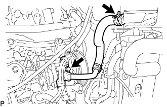
DISCONNECT PRESSURE FEED TUBE ASSEMBLY (w/ Variable Flow Control Solenoid Valve)
DISCONNECT SUCTION HOSE (w/o Variable Flow Control Solenoid Valve)
REMOVE NO. 1 OIL RESERVOIR TO PUMP HOSE (w/ Variable Flow Control Solenoid Valve)
Vane Pump (For 1Ur-Fe) -- Removal |
| 1. PRECAUTION |
- NOTICE:
- After turning the engine switch off, waiting time may be required before disconnecting the cable from the battery terminal. Therefore, make sure to read the disconnecting the cable from the battery terminal notice before proceeding with work (Click here).
| 2. DISCONNECT CABLE FROM NEGATIVE BATTERY TERMINAL |
- CAUTION:
- Wait at least 90 seconds after disconnecting the cable from the negative (-) battery terminal to disable the SRS system.
- NOTICE:
- When disconnecting the cable, some systems need to be initialized after the cable is reconnected (Click here).
| 3. REMOVE FRONT WHEEL RH |
| 4. REMOVE FRONT FENDER APRON TRIM PACKING A |
Remove the 3 bolts and 2 screws.
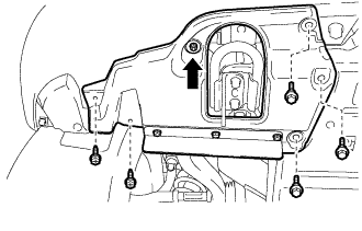 |
Turn the clip indicated by the arrow in the illustration to remove the front fender splash shield sub-assembly RH.
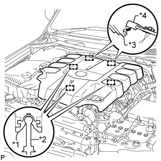
| 5. REMOVE V-BANK COVER SUB-ASSEMBLY |
Raise the front of the V-bank cover to detach the 3 pins. Then remove the 2 V-bank cover hooks from the bracket, and remove the V-bank cover.
Text in Illustration *1 Grommet *2 Pin *3 Hook *4 Bracket
 |
| 6. REMOVE AIR CLEANER AND HOSE |
Disconnect the No. 2 PCV hose and No. 1 air hose.
 |
Disconnect the mass air flow meter connector and detach the clamp.
Remove the 3 bolts and loosen the hose clamp, and then remove the air cleaner and hose.
| 7. REMOVE FAN AND GENERATOR V BELT |
While turning the belt tensioner counterclockwise, align the service hole for the belt tensioner and the belt tensioner fixing position, and then insert a bar with a diameter of 5 mm (0.197 in.) into the service hole to fix the belt tensioner in place.
Text in Illustration *1 Bar *2 Service Hole *a Turn - HINT:
- The pulley bolt for the belt tensioner has a left-hand thread.
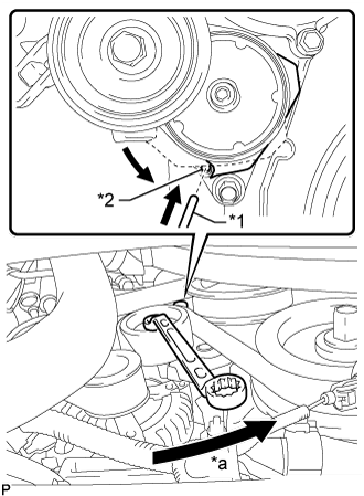 |
Remove the fan and generator V belt.
| 8. DRAIN POWER STEERING FLUID |
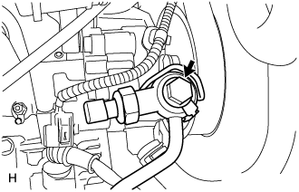
| 9. DISCONNECT POWER STEERING OIL PRESSURE SENSOR CONNECTOR (w/o Variable Flow Control Solenoid Valve) |
Detach the wire harness clamp and disconnect the connector.
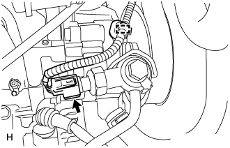 |
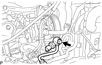
| 10. DISCONNECT PRESSURE FEED TUBE (w/o Variable Flow Control Solenoid Valve) |
Remove the union bolt and disconnect the pressure feed tube.
 |
Remove the gasket.
| 11. DISCONNECT PRESSURE FEED TUBE ASSEMBLY (w/ Variable Flow Control Solenoid Valve) |
Detach the 2 wire harness clamps and disconnect the 2 connectors.
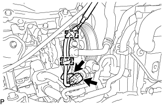 |
Remove the union bolt and disconnect the pressure feed tube.
 |
Remove the gasket.
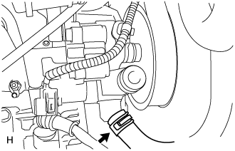
| 12. DISCONNECT SUCTION HOSE (w/o Variable Flow Control Solenoid Valve) |
Slide the clip and disconnect the suction hose from the vane pump.
 |
| 13. REMOVE NO. 1 OIL RESERVOIR TO PUMP HOSE (w/ Variable Flow Control Solenoid Valve) |
Slide the clip and disconnect the No. 1 oil reservoir to pump hose from the oil reservoir.
 |
Remove the bolt and No. 1 oil reservoir to pump hose.
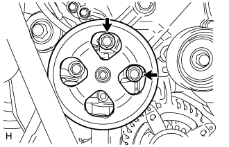
| 14. REMOVE VANE PUMP ASSEMBLY |
Remove the 2 bolts and vane pump.
 |