Vehicle Stability Control System Vsc Off Indicator Light Remains On
Brake. Land Cruiser. Urj200, 202 Grj200 Vdj200
DESCRIPTION
WIRING DIAGRAM
INSPECTION PROCEDURE
INSPECT IF SKID CONTROL ECU CONNECTOR IS SECURELY CONNECTED
CHECK CAN COMMUNICATION LINE
CHECK DTC (CAN COMMUNICATION SYSTEM)
READ VALUE USING GTS (TRC/VSC OFF MODE)
INSPECT VSC OFF SWITCH OR INTEGRATION CONTROL AND PANEL ASSEMBLY
CHECK HARNESS AND CONNECTOR (SKID CONTROL ECU - VSC OFF SWITCH)
VEHICLE STABILITY CONTROL SYSTEM - VSC OFF Indicator Light Remains ON |
DESCRIPTION
- w/o Entry and Start System:
Operation of the VSC OFF switch changes the vehicle between normal mode, TRC OFF mode and VSC OFF mode. During normal mode, pressing the VSC OFF switch for a short amount of time changes vehicle to TRC OFF mode. When the vehicle is stopped, pressing the VSC OFF switch for 3 seconds or more changes the vehicle to VSC OFF mode.
- w/ Entry and Start System:
Operation of the VSC OFF switch (integration control and panel assembly) changes the vehicle between normal mode, TRC OFF mode and VSC OFF mode. During normal mode, pressing the VSC OFF switch (integration control and panel assembly) for a short amount of time changes vehicle to TRC OFF mode. When the vehicle is stopped, pressing the VSC OFF switch (integration control and panel assembly) for 3 seconds or more changes the vehicle to VSC OFF mode.
When the transfer is in L4, the VSC OFF indicator light turns on.
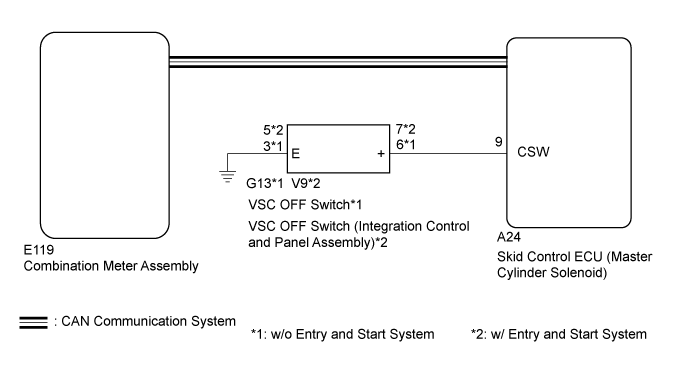
WIRING DIAGRAM
INSPECTION PROCEDURE
- NOTICE:
- After replacing the master cylinder solenoid, perform zero point calibration and store the system information (Click here).
- As there may be malfunctions in the transfer system related to when the transfer operates in L4, check the transfer system first (Click here).
| 1.INSPECT IF SKID CONTROL ECU CONNECTOR IS SECURELY CONNECTED |
Check the skid control ECU (master cylinder solenoid) connector connection.
- OK:
- The connector is securely connected.
| | CONNECT CONNECTOR TO ECU CORRECTLY |
|
|
| 2.CHECK CAN COMMUNICATION LINE |
Turn the ignition switch off.
Connect the GTS to the DLC3.
Turn the ignition switch to ON and the GTS on.
Select "CAN Bus Check" from the System Selection Menu screen, and follow the prompts on the screen to inspect the CAN Bus.
- OK:
- "CAN Bus Check" indicates no malfunctions in CAN communication.
ResultResult
| Proceed to
|
OK
| A
|
NG (for LHD (with Central Gateway ECU))
| B
|
NG (for LHD (without Central Gateway ECU))
| C
|
NG (for RHD (with Central Gateway ECU))
| D
|
NG (for RHD (without Central Gateway ECU))
| E
|
| | GO TO CAN COMMUNICATION SYSTEM (HOW TO PROCEED WITH TROUBLESHOOTING) (Click here) |
|
|
| | GO TO CAN COMMUNICATION SYSTEM (HOW TO PROCEED WITH TROUBLESHOOTING) (Click here) |
|
|
| | GO TO CAN COMMUNICATION SYSTEM (HOW TO PROCEED WITH TROUBLESHOOTING) (Click here) |
|
|
| | GO TO CAN COMMUNICATION SYSTEM (HOW TO PROCEED WITH TROUBLESHOOTING) (Click here) |
|
|
| 3.CHECK DTC (CAN COMMUNICATION SYSTEM) |
Turn the ignition switch off.
Connect the GTS to the DLC3.
Turn the ignition switch to ON and the GTS on.
for LHD (with Central Gateway ECU):
Check for DTCs (Click here).
for LHD (without Central Gateway ECU):
Check for DTCs (Click here).
for RHD (with Central Gateway ECU):
Check for DTCs (Click here).
for RHD (without Central Gateway ECU):
Check for DTCs (Click here).
ResultResult
| Proceed to
|
CAN DTC is not output
| A
|
CAN DTC is output (for LHD (with Central Gateway ECU))
| B
|
CAN DTC is output (for LHD (without Central Gateway ECU))
| C
|
CAN DTC is output (for RHD (with Central Gateway ECU))
| D
|
CAN DTC is output (for RHD (without Central Gateway ECU))
| E
|
| | GO TO CAN COMMUNICATION SYSTEM (HOW TO PROCEED WITH TROUBLESHOOTING) (Click here) |
|
|
| | GO TO CAN COMMUNICATION SYSTEM (HOW TO PROCEED WITH TROUBLESHOOTING) (Click here) |
|
|
| | GO TO CAN COMMUNICATION SYSTEM (HOW TO PROCEED WITH TROUBLESHOOTING) (Click here) |
|
|
| | GO TO CAN COMMUNICATION SYSTEM (HOW TO PROCEED WITH TROUBLESHOOTING) (Click here) |
|
|
| 4.READ VALUE USING GTS (TRC/VSC OFF MODE) |
Turn the ignition switch off.
Connect the GTS to the DLC3.
Turn the ignition switch to ON.
Turn the GTS on.
Enter the following menus: Chassis / ABS/VSC/TRC / Data List.
ABS/VSC/TRCTester Display
| Measurement Item/Range
| Normal Condition
| Diagnostic Note
|
TRC/VSC Off Mode
| TRC/VSC off mode/ Normal, TRC OFF, Unknown or VSC OFF
| Normal: Normal mode
TRC OFF: TRC OFF mode
VSC OFF: VSC OFF mode
| -
|
Check that the mode display changes according to VSC OFF switch*1 or VSC OFF switch (integration control and panel assembly)*2 operation.
- *1: w/o Entry and Start System
- *2: w/ Entry and Start System
- OK:
- Display changes according to switch operation.
| OK |
|
|
|
| GO TO METER / GAUGE SYSTEM (HOW TO PROCEED WITH TROUBLESHOOTING) (Click here) |
|
| 5.INSPECT VSC OFF SWITCH OR INTEGRATION CONTROL AND PANEL ASSEMBLY |
w/o Entry and Start System:
Remove the VSC OFF switch (Click here).
w/ Entry and Start System:
Remove the VSC OFF switch (integration control and panel assembly) (Click here).
w/o Entry and Start System:
Inspect the VSC OFF switch (Click here).
w/ Entry and Start System:
Inspect the VSC OFF switch (integration control and panel assembly) (Click here).
ResultResult
| Proceed to
|
OK
| A
|
NG (w/o Entry and Start System)
| B
|
NG (w/ Entry and Start System)
| C
|
| |
|
| | REPLACE INTEGRATION CONTROL AND PANEL ASSEMBLY (Click here) |
|
|
| 6.CHECK HARNESS AND CONNECTOR (SKID CONTROL ECU - VSC OFF SWITCH) |
Turn the ignition switch off.
Disconnect the A24 skid control ECU (master cylinder solenoid) connector.
Disconnect the G13 VSC OFF switch*1 or V9 VSC OFF switch (integration control and panel assembly)*2 connector.
- *1: w/o Entry and Start System
- *2: w/ Entry and Start System
Measure the resistance according to the value(s) in the table below.
- Standard Resistance:
w/o Entry and Start System:Tester Connection
| Condition
| Specified Condition
|
A24-9 (CSW) - G13-6 (+)
| Always
| Below 1 Ω
|
A24-9 (CSW) - Body ground
| Always
| 10 kΩ or higher
|
G13-3 (E)- Body ground
| Always
| Below 1 Ω
|
w/ Entry and Start System:Tester Connection
| Condition
| Specified Condition
|
A24-9 (CSW) - V9-7 (+)
| Always
| Below 1 Ω
|
A24-9 (CSW) - Body ground
| Always
| 10 kΩ or higher
|
V9-5 (E)- Body ground
| Always
| Below 1 Ω
|
ResultResult
| Proceed to
|
NG
| A
|
OK (for LHD)
| B
|
OK (for RHD)
| C
|
| A |
|
|
|
| REPAIR OR REPLACE HARNESS OR CONNECTOR |
|