Dtc C1426 Stop Light Switch Off Stuck Malfunction
Brake. Land Cruiser. Urj200, 202 Grj200 Vdj200
DESCRIPTION
WIRING DIAGRAM
INSPECTION PROCEDURE
CHECK BRAKE PEDAL AND STOP LIGHT SWITCH INSTALLATION
CHECK STOP LIGHT OPERATION
READ VALUE USING GTS (STOP LIGHT SW)
RECONFIRM DTC
INSPECT STOP LIGHT SWITCH ASSEMBLY
CHECK HARNESS AND CONNECTOR (STP TERMINAL)
RECONFIRM DTC
CHECK HARNESS AND CONNECTOR (STP TERMINAL)
DTC C1426 Stop Light Switch OFF Stuck Malfunction |
DESCRIPTION
The skid control ECU (master cylinder solenoid) inputs the stop light signal and brake operation condition. When the brake pedal is depressed and the stop light switch signal is not input, C1426 is output.DTC Code
| DTC Detection Condition
| Trouble Area
|
C1426
| When both of the following conditions are met:
- After the vehicle reaches 35 km/h or more, the PMC terminal voltage is continuously 0.86 V or higher for 1 second or more at a vehicle speed of 3 km/h or more.
- The stop light switch signal is not input for 5 seconds or more with the PMC terminal voltage at 0.86 V or higher while the IG terminal voltage is 9.5 V or higher and the vehicle speed is 3 km/h or less for a period of less than 0.6 seconds.
| - Wire harness or connector
- STOP fuse
- Stop light switch assembly
- Skid Control ECU (Master cylinder solenoid)
|
WIRING DIAGRAM
Refer to DTC C1425 (Click here).
INSPECTION PROCEDURE
- NOTICE:
- When replacing the skid control ECU (master cylinder solenoid), perform zero point calibration and store system information. (Click here).
- Inspect the fuses for circuits related to this system before performing the following inspection procedure.
| 1.CHECK BRAKE PEDAL AND STOP LIGHT SWITCH INSTALLATION |
Turn the ignition switch off.
Check the brake pedal height and stop light switch assembly installation (for LHD: See Click here, for RHD: Click here).
- OK:
- The brake pedal height and stop light switch installation are normal.
ResultResult
| Proceed to
|
OK
| A
|
NG (for LHD)
| B
|
NG (for RHD)
| C
|
| | ADJUST BRAKE PEDAL AND STOP LIGHT SWITCH INSTALLATION (Click here) |
|
|
| | ADJUST BRAKE PEDAL AND STOP LIGHT SWITCH INSTALLATION (Click here) |
|
|
| 2.CHECK STOP LIGHT OPERATION |
Check that the all stop lights come on when the brake pedal is depressed, and go off when the brake pedal is released.
- OK:
Condition
| Illumination Condition
|
Brake pedal depressed
| On
|
Brake pedal released
| Off
|
| 3.READ VALUE USING GTS (STOP LIGHT SW) |
Turn the ignition switch off.
Connect the GTS to the DLC3.
Turn the ignition switch ON.
Turn the GTS on.
Enter the following menus: Chassis / ABS/VSC/TRC / Data List.
ABS/VSC/TRCTester Display
| Measurement Item/Range
| Normal Condition
| Diagnostic Note
|
Stop Light SW
| Stop light switch/ ON or OFF
| ON: Brake pedal depressed
OFF: Brake pedal released
| -
|
Check that the stop light switch display observed on the GTS changes according to brake pedal operation.
- OK:
- The GTS displays ON or OFF according to brake pedal operation.
Turn the ignition switch off.
Clear the DTCs (Click here).
Start the engine.
Depress the brake pedal several times to test the stop light circuit.
Check if the same DTC is output (Click here).
ResultResult
| Proceed to
|
DTC C1426 is not output
| A
|
DTC C1426 is output (for LHD)
| B
|
DTC C1426 is output (for RHD)
| C
|
- HINT:
- If troubleshooting has been carried out according to Problem Symptoms Table, refer back to the table and proceed to the next step.
| 5.INSPECT STOP LIGHT SWITCH ASSEMBLY |
Check the stop light switch assembly (Click here).
- OK:
- The stop light switch assembly is normal.
| 6.CHECK HARNESS AND CONNECTOR (STP TERMINAL) |
Turn the ignition switch off.
Disconnect the skid control ECU (master cylinder solenoid) connector.
Measure the voltage according to the value(s) in the table below.
- Standard Voltage:
Tester Connection
| Condition
| Specified Condition
|
A24-7 (STP) - Body ground
| Brake pedal depressed
| 8 to 14 V
|
Brake pedal released
| Below 1.5 V
|
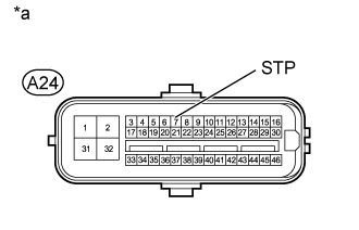
Text in Illustration*a
| Front view of wire harness connector
(to Skid Control ECU [Master Cylinder Solenoid])
|
| | REPAIR OR REPLACE HARNESS OR CONNECTOR (STP CIRCUIT) |
|
|
Reconnect the A24 skid control ECU (master cylinder solenoid) connector.
Clear the DTCs (Click here).
Turn the ignition switch off.
Start the engine.
Depress the brake pedal several times to test the stop light circuit.
Check if the same DTC is output (Click here).
ResultResult
| Proceed to
|
DTC C1426 is not output
| A
|
DTC C1426 is output
| B
|
| | INSPECT LIGHTING SYSTEM (STOP LIGHT CIRCUIT) (Click here) |
|
|
| 8.CHECK HARNESS AND CONNECTOR (STP TERMINAL) |
Turn the ignition switch off.
Disconnect the skid control ECU (master cylinder solenoid) connector.
Measure the voltage according to the value(s) in the table below.
- Standard Voltage:
Tester Connection
| Condition
| Specified Condition
|
A24-7 (STP) - Body ground
| Brake pedal depressed
| 8 to 14 V
|
Brake pedal released
| Below 1.5 V
|
Text in Illustration*a
| Front view of wire harness connector
(to Skid Control ECU [Master Cylinder Solenoid])
|
ResultResult
| Proceed to
|
OK (for LHD)
| A
|
OK (for RHD)
| B
|
NG
| C
|
| |
|
| | REPAIR OR REPLACE HARNESS OR CONNECTOR (STP CIRCUIT) |
|
|