Dtc C1243 Acceleration Sensor Stuck Malfunction
Brake. Land Cruiser. Urj200, 202 Grj200 Vdj200
DESCRIPTION
WIRING DIAGRAM
INSPECTION PROCEDURE
CHECK DECELERATION SENSOR INSTALLATION
READ VALUE USING GTS (DECELERATION SENSOR)
CHECK DTC
INSPECT DECELERATION SENSOR
CHECK HARNESS AND CONNECTOR (SKID CONTROL ECU - DECELERATION SENSOR)
CHECK DTC
DTC C1243 Acceleration Sensor Stuck Malfunction |
DTC C1245 Acceleration Sensor Output Malfunction |
DTC C1279 Acceleration Sensor Output Voltage Malfunction (Test Mode DTC) |
DTC C1381 Acceleration Sensor Power Supply Voltage Malfunction |
DTC C1418 Open or Short in Acceleration Sensor Circuit |
DESCRIPTION
The skid control ECU (master cylinder solenoid) receives signals from the deceleration sensor. If the sensor functions abnormally, the ABS warning light turns on.DTC Code
| DTC Detection Condition
| Trouble Area
|
C1243
| The following condition repeats 16 times.
- Sensor signal do not change when the vehicle decelerates from 30 km/h (19 mph) to 0 km/h (0 mph).
| - Deceleration sensor
- Harness or connector
- Skid control ECU (Master cylinder solenoid)
|
C1245
| The following condition continues for at least 60 seconds.
- The difference between the values calculated from the deceleration sensor value and vehicle speed exceeds 0.35 G.
|
C1381
| At a vehicle speed of more than 3 km/h (2 mph), the deceleration sensor power source malfunction signal is received for 10 seconds or more.
|
C1418
| One of the following conditions is met when the voltage at terminal IG1 is 9.5 V or higher:
- The power supply voltage of the deceleration sensor is outside the range of 4.4 to 5.6 V for 1.2 seconds or more.
- The value of GL1 is outside the range of -1.5 to 1.5 G for 1.2 seconds or more.
- A deceleration sensor open circuit occurs 7 times or more.
|
C1279
| Stored during test mode.
|
WIRING DIAGRAM
INSPECTION PROCEDURE
- NOTICE:
- After replacing the deceleration sensor, perform zero point calibration (Click here).
| 1.CHECK DECELERATION SENSOR INSTALLATION |
Check that the deceleration sensor is installed properly.
ResultResult
| Proceed to
|
The sensor is tightened to the specified torque.
The sensor is not tilted.
| A
|
The sensor is not tightened to the specified torque.
Or the sensor is tilted.
| B
|
| | INSTALL DECELERATION SENSOR CORRECTLY (Click here) |
|
|
| 2.READ VALUE USING GTS (DECELERATION SENSOR) |
Turn the ignition switch off.
Connect the GTS to the DLC3.
Start the engine.
Turn the GTS on.
Enter the following menus: Chassis / ABS/VSC/TRC / Data List.
ABS/VSC/TRCTester Display
| Measurement Item/Range
| Normal Condition
| Diagnostic Note
|
Deceleration Sensor
| Deceleration sensor reading / min.: -18.525 m/s2, max.: 18.387 m/s2
| Approximately -1.28 to 1.27 m/s2 while stationary
| The reading changes when the vehicle is bounced.
|
Check the Data List for proper functioning of the deceleration sensor.
- OK:
- Deceleration value changes.
Install the deceleration sensor to the vehicle.
Clear the DTCs (Click here).
Turn the ignition switch off.
Drive the vehicle at 6 km/h (4 mph) or more.
Check if the same DTCs are output (Click here).
ResultResult
| Proceed to
|
DTC is not output
| A
|
DTC is output (for LHD)
| B
|
DTC is output (for RHD)
| C
|
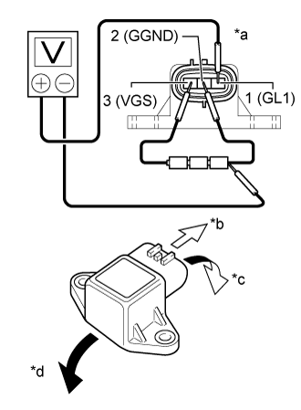
| 4.INSPECT DECELERATION SENSOR |
Remove the deceleration sensor (Click here).
Connect 3 dry cell batteries of 1.5 V in series.
- NOTICE:
- Do not apply 6 V or more to terminals 3 (VGS) and 2 (GGND).
Check the output voltage of terminal 1 (GL1) when the sensor is tilted forward and rearward.
- Standard Voltage:
Tester Connection
| Condition
| Specified Condition
|
1 (GL1) - Battery negative (-) lead
| Horizontal
| Approximately 2.5 V
|
Tilted forward
| Approximately 0.5 to 2.5 V
|
Tilted rearward
| Approximately 2.5 to 4.5 V
|
Text in Illustration *a
| Component without harness connected
(Deceleration Sensor)
|
*b
| Front
|
*c
| Tilted forward
|
*d
| Tilted rearward
|
- HINT:
- If the sensor is tilted too much, it may output the wrong value.
- If the voltage drops, the sensor should be replaced with a new one.
- When replacing the sensor, it should not be placed upside down.
| 5.CHECK HARNESS AND CONNECTOR (SKID CONTROL ECU - DECELERATION SENSOR) |
Disconnect the A24 skid control ECU (master cylinder solenoid) connector.
Disconnect the E88 deceleration sensor connector.
Measure the resistance according to the value(s) in the table below.
- Standard Resistance:
Tester Connection
| Condition
| Specified Condition
|
A24-39 (GL1) - E88-1 (GL1)
| Always
| Below 1 Ω
|
A24-23 (GGND) - E88-2 (GGND)
| Always
| Below 1 Ω
|
A24-22 (VGS) - E88-3 (VGS)
| Always
| Below 1 Ω
|
E88-1 (GL1) - Body ground
| Always
| 10 kΩ or higher
|
E88-2 (GGND) - Body ground
| Always
| 10 kΩ or higher
|
E88-3 (VGS) - Body ground
| Always
| 10 kΩ or higher
|
| | REPAIR OR REPLACE HARNESS OR CONNECTOR |
|
|
Install the deceleration sensor to the vehicle.
Clear the DTCs (Click here).
Turn the ignition switch off.
Drive the vehicle at 6 km/h (4 mph) or more.
Check if the same DTCs are output (Click here).
ResultResult
| Proceed to
|
DTC is not output
| A
|
DTC is output (for LHD)
| B
|
DTC is output (for RHD)
| C
|