Tire Pressure Warning System Tc And Cg Terminal Circuit
Suspension. Land Cruiser. Urj200, 202 Grj200 Vdj200
DESCRIPTION
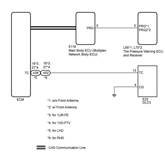
WIRING DIAGRAM
INSPECTION PROCEDURE
CHECK CAN COMMUNICATION SYSTEM
CHECK DTC (C2179/79)
INSPECT DLC3 (TC VOLTAGE)
REPLACE ECM
CHECK HARNESS AND CONNECTOR (TC of DLC3 - ECM)
CHECK HARNESS AND CONNECTOR (CG of DLC3 - BODY GROUND)
REPLACE ECM
TIRE PRESSURE WARNING SYSTEM - TC and CG Terminal Circuit |
DESCRIPTION
DTC output mode is set by connecting terminals 13 (TC) and 4 (CG) of the DLC3. The DTCs are indicated by the blinking of the tire pressure warning light.
WIRING DIAGRAM
INSPECTION PROCEDURE
| 1.CHECK CAN COMMUNICATION SYSTEM |
Check if a CAN communication system DTC is output (for LHD with Central Gateway ECU: Click here, for LHD without Central Gateway ECU: Click here, for RHD with Central Gateway ECU: Click here, for RHD without Central Gateway ECU: Click here).
- Result:
Result
| Proceed to
|
DTC is not output.
| A
|
DTC is output.
| for LHD with Central Gateway ECU
| B
|
for LHD without Central Gateway ECU
| C
|
for RHD with Central Gateway ECU
| D
|
for RHD without Central Gateway ECU
| E
|
Check if DTC C2179/79 is output (Click here).
- Result:
Result
| Proceed to
|
DTC C2179/79 is not output.
| A
|
DTC C2179/79 is output.
| B
|
| 3.INSPECT DLC3 (TC VOLTAGE) |
Turn the engine switch off.
Measure the voltage according to the value(s) in the table below.
- Standard Voltage:
Tester Connection
| Switch Condition
| Specified Condition
|
E22-13 (TC) - E22-4 (CG)
| Engine switch on (IG)
| 11 to 14 V
|
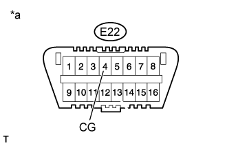
Text in Illustration*a
| Front view of DLC3
|
- SST
- 09843-18040
Turn the engine switch off.
Replace the ECM (for 1UR-FE: Click here, for 1VD-FTV: Click here).
Text in Illustration*a
| Front view of DLC3
|
Using SST, connect terminals 13 (TC) and 4 (CG) of the DLC3.
Turn the engine switch to on (IG).
Check that the tire pressure warning light is blinking.
- OK:
- The tire pressure warning light is blinking.
- HINT:
- If troubleshooting has been carried out according to Problem Symptoms Table, refer back to the table and proceed to the next step before replacing the part (Click here).
| | REPLACE TIRE PRESSURE WARNING ECU
AND RECEIVER (Click here) |
|
|
| 5.CHECK HARNESS AND CONNECTOR (TC of DLC3 - ECM) |
Turn the engine switch off.
Disconnect the A38*1 or A52*2 ECM connector.
- *1: for LHD
- *2: for RHD
Measure the resistance according to the value(s) in the table below.
- Standard Resistance:
for 1UR-FETester Connection
| Condition
| Specified Condition
|
E22-13 (TC) - A38-16 (TC)*1
E22-13 (TC) - A52-16 (TC)*2
| Always
| Below 1 Ω
|
E22-13 (TC) or A38-16 (TC)*1 - Body ground
E22-13 (TC) or A52-16 (TC)*2 - Body ground
| Always
| 10 kΩ or higher
|
for 1VD-FTVTester Connection
| Condition
| Specified Condition
|
E22-13 (TC) - A38-27 (TC)*1
E22-13 (TC) - A52-27 (TC)*2
| Always
| Below 1 Ω
|
E22-13 (TC) or A38-27 (TC)*1 - Body ground
E22-13 (TC) or A52-27 (TC)*2 - Body ground
| Always
| 10 kΩ or higher
|
- *1: for LHD
- *2: for RHD
| | REPAIR OR REPLACE HARNESS OR CONNECTOR |
|
|
| 6.CHECK HARNESS AND CONNECTOR (CG of DLC3 - BODY GROUND) |
Measure the resistance according to the value(s) in the table below.
- Standard Resistance:
Tester Connection
| Condition
| Specified Condition
|
E22-4 (CG) - Body ground
| Always
| Below 1 Ω
|
Text in Illustration*a
| Front view of DLC3
|
| | REPAIR OR REPLACE HARNESS OR CONNECTOR |
|
|
- SST
- 09843-18040
Turn the engine switch off.
Replace the ECM (for 1UR-FE: Click here, for 1VD-FTV: Click here).
Text in Illustration*a
| Front view of DLC3
|
Using SST, connect terminals 13 (TC) and 4 (CG) of the DLC3.
Turn the engine switch to on (IG).
Check that the tire pressure warning light is blinking.
- OK:
- The tire pressure warning light is blinking.
- HINT:
- If troubleshooting has been carried out according to Problem Symptoms Table, refer back to the table and proceed to the next step before replacing the part (Click here).
| | REPLACE TIRE PRESSURE WARNING ECU
AND RECEIVER (Click here) |
|
|