CHECK HARNESS AND CONNECTOR (TIRE PRESSURE WARNING ECU AND RECEIVER - TIRE PRESSURE WARNING ANTENNA)
CHECK TIRE PRESSURE WARNING ANTENNA RECEPTION
REPLACE TIRE PRESSURE WARNING ANTENNA
CHECK TEST MODE DTC (C2195/95)
DTC C2195/95 Multi-receiver Antenna Circuit (Test Mode DTC) |
DESCRIPTION
This DTC is used for detecting open circuits and radio wave frequency mismatches in the tire pressure warning antenna.| DTC No. | DTC Detection Condition | Trouble Area |
| C2195/95 | Test mode procedure is performed. |
|
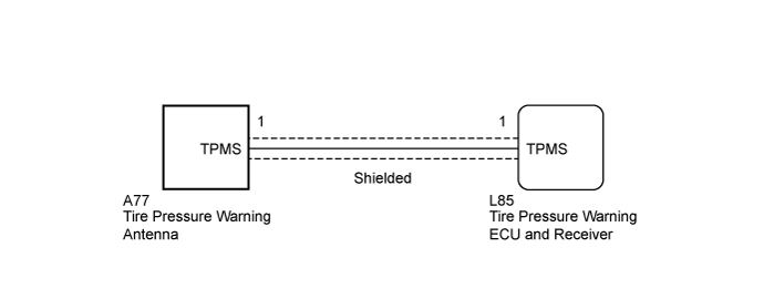
WIRING DIAGRAM
INSPECTION PROCEDURE
- NOTICE:
- When replacing the tire pressure warning ECU and receiver, read the transmitter IDs stored in the old ECU using the GTS and write them down before removal.
- It is necessary to perform initialization (Click here) after registration (Click here) of the transmitter IDs into the tire pressure warning ECU and receiver if the ECU has been replaced.
| 1.CHECK HARNESS AND CONNECTOR (TIRE PRESSURE WARNING ECU AND RECEIVER - TIRE PRESSURE WARNING ANTENNA) |
Disconnect the L85 tire pressure warning ECU and receiver connector.
Disconnect the A77 tire pressure warning antenna connector.
Measure the resistance according to the value(s) in the table below.
- HINT:
- Because the coaxial cable that is used for the tire pressure warning antenna consists of a center conductor and an outer shielding layer (-), this measurement should be performed to ensure that there is no malfunction in the coaxial cable.
- Standard Resistance:
Tester Connection Condition Specified Condition L85-1 (TPMS) - A77-1 (TPMS) Always Below 1 Ω L85-1 (shielded wire) - A77-1 (shielded wire) Always Below 1 Ω L85-1 (TPMS) - A77-1 (shielded wire) Always 10 kΩ or higher L85-1 (shielded wire) - A77-1 (TPMS) Always 10 kΩ or higher
|
| ||||
| OK | |
| 2.CHECK TIRE PRESSURE WARNING ANTENNA RECEPTION |
Set the tire pressure to the specified value (Click here).
Turn the engine switch off.
Connect the L85 tire pressure warning ECU and receiver connector.
Connect the A77 tire pressure warning antenna connector.
- NOTICE:
- Be sure to disconnect the connector on the tire pressure warning antenna.
Connect the GTS to the DLC3.
Turn the engine switch on (IG).
Turn the GTS on.
Enter the following menus: Chassis / Tire Pressure Monitor / Data List.
Check the values by referring to the table below.
Tire Pressure Monitor Tester Display Measurement Item/Range Normal Condition Diagnostic Note ID 1 Tire Inflation Pressure ID1 tire inflation pressure/
min.: Absolute pressure (abs) / 0 kPa (0 kgf/cm2, 0 psi), Relative pressure (Gauge) / 0 kPa (0 kgf/cm2, 0 psi)
max.: Absolute pressure (abs) / 480 kPa (4.9 kgf/cm2, 70 psi), Relative pressure (Gauge) / 380 kPa (3.9 kgf/cm2, 55 psi)Actual tire inflation pressure If N/A is displayed, data has not been received.* ID 2 Tire Inflation Pressure ID2 tire inflation pressure/
min.: Absolute pressure (abs) / 0 kPa (0 kgf/cm2, 0 psi), Relative pressure (Gauge) / 0 kPa (0 kgf/cm2, 0 psi)
max.: Absolute pressure (abs) / 480 kPa (4.9 kgf/cm2, 70 psi), Relative pressure (Gauge) / 380 kPa (3.9 kgf/cm2, 55 psi)Actual tire inflation pressure If N/A is displayed, data has not been received.* ID 3 Tire Inflation Pressure ID3 tire inflation pressure/
min.: Absolute pressure (abs) / 0 kPa (0 kgf/cm2, 0 psi), Relative pressure (Gauge) / 0 kPa (0 kgf/cm2, 0 psi)
max.: Absolute pressure (abs) / 480 kPa (4.9 kgf/cm2, 70 psi), Relative pressure (Gauge) / 380 kPa (3.9 kgf/cm2, 55 psi)Actual tire inflation pressure If N/A is displayed, data has not been received.* ID 4 Tire Inflation Pressure ID4 tire inflation pressure/
min.: Absolute pressure (abs) / 0 kPa (0 kgf/cm2, 0 psi), Relative pressure (Gauge) / 0 kPa (0 kgf/cm2, 0 psi)
max.: Absolute pressure (abs) / 480 kPa (4.9 kgf/cm2, 70 psi), Relative pressure (Gauge) / 380 kPa (3.9 kgf/cm2, 55 psi)Actual tire inflation pressure If N/A is displayed, data has not been received.* ID 5 Tire Inflation Pressure ID5 tire inflation pressure/
min.: Absolute pressure (abs) / 0 kPa (0 kgf/cm2, 0 psi), Relative pressure (Gauge) / 0 kPa (0 kgf/cm2, 0 psi)
max.: Absolute pressure (abs) / 480 kPa (4.9 kgf/cm2, 70 psi), Relative pressure (Gauge) / 380 kPa (3.9 kgf/cm2, 55 psi)Actual tire inflation pressure If N/A is displayed, data has not been received.* - HINT:
- *: It may take a few minutes until the values are displayed.
- The wheel position cannot be determined from ID1 through ID5 on the Data List.
Rapidly reduce the tire pressure for each wheel at least 40 kPa (0.4 kgf/cm2, 5.8 psi) within 30 seconds.
Check that each tire pressure value displayed on the GTS has changed.
- Result:
Result Proceed to Tire pressure data does not change A Tire pressure of at least 1 wheel changes B
|
| ||||
| A | |
| 3.REPLACE TIRE PRESSURE WARNING ANTENNA |
Replace the tire pressure warning antenna (Click here).
| NEXT | |
| 4.CHECK TEST MODE DTC (C2195/95) |
Turn the engine switch off.
Connect the GTS to the DLC3.
Turn the engine switch on (IG).
Turn the GTS on.
Enter the following menus: Chassis / Tire Pressure Monitor / Utility / Signal Check.
Perform the test mode inspection (Click here).
- Result:
Result Proceed to DTC C2195/95 is not cleared A DTC 2195/95 is cleared (When performing the test mode inspection after replacing the tire pressure warning antenna (for Rear Side) or tire pressure warning antenna) B DTC 2195/95 is cleared (When performing the test mode inspection after the tire pressures have changed as a result of the tire pressure warning antenna reception check) C
|
| ||||
|
| ||||
| A | ||
| ||