REMOVE LOWER CENTER INSTRUMENT CLUSTER FINISH PANEL SUB-ASSEMBLY
REMOVE NO. 1 INSTRUMENT PANEL UNDER COVER SUB-ASSEMBLY (w/ Floor Under Cover)
REMOVE DRIVER SIDE KNEE AIRBAG ASSEMBLY (w/ Driver Side Knee Airbag)
REMOVE LOWER INSTRUMENT PANEL SUB-ASSEMBLY (w/o Driver Side Knee Airbag)
REMOVE NO. 2 INSTRUMENT PANEL UNDER COVER SUB-ASSEMBLY (w/ Floor Under Cover)
REMOVE FRONT PASSENGER SIDE KNEE AIRBAG ASSEMBLY (w/ Passenger Side Knee Airbag)
REMOVE LOWER INSTRUMENT PANEL (w/o Passenger Side Knee Airbag)
Front Acceleration Sensor -- Removal |
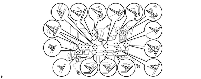
| 1. TABLE OF BOLT, SCREW AND NUT |
- HINT:
- All bolts, screws and nuts relevant to installing and removing the instrument panel are shown along with their alphabet code in the table below.

| 2. DISCONNECT CABLE FROM NEGATIVE BATTERY TERMINAL |
- NOTICE:
- When disconnecting the cable, some systems need to be initialized after the cable is reconnected (Click here).
| 3. REMOVE NO. 2 INSTRUMENT PANEL FINISH PANEL CUSHION |
Place protective tape as shown in the illustration.
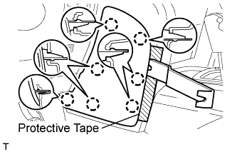 |
Using a moulding remover, detach the 7 claws and remove the panel cushion.
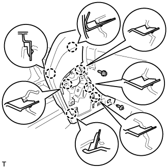
| 4. REMOVE LOWER INSTRUMENT PANEL PAD SUB-ASSEMBLY LH |
Remove the clip.
 |
Remove the screw.
Detach the 8 claws.
Remove the panel pad and disconnect the connectors and 2 clamps.
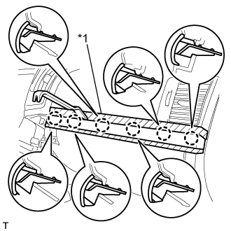
| 5. REMOVE NO. 1 INSTRUMENT PANEL FINISH PANEL CUSHION |
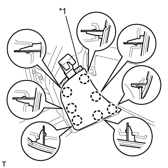 |
Put protective tape around the No. 1 instrument panel finish panel cushion.
Text in Illustration *1 Protective Tape
Using a moulding remover, detach the 7 claws and remove the No. 1 instrument panel finish panel cushion.
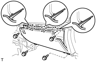
| 6. REMOVE LOWER INSTRUMENT PANEL PAD SUB-ASSEMBLY RH |
 |
Remove the clip and screw.
Detach the 7 claws and remove the lower instrument panel pad sub-assembly.
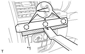
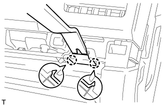
| 7. REMOVE LOWER CENTER INSTRUMENT CLUSTER FINISH PANEL SUB-ASSEMBLY |
 |
Detach the 7 claws.
Disconnect the connectors and remove the lower center instrument cluster finish panel sub-assembly.
| 8. REMOVE INSTRUMENT SIDE PANEL LH |
 |
Place protective tape as shown in the illustration.
Text in Illustration *1 Protective Tape
Using a moulding remover, detach the 6 claws and remove the instrument side panel.
| 9. REMOVE NO. 1 INSTRUMENT CLUSTER FINISH PANEL GARNISH |
 |
Place protective tape as shown in the illustration.
Text in Illustration *1 Protective Tape
Using a moulding remover, detach the 3 claws and remove the No. 1 instrument cluster finish panel garnish.
| 10. REMOVE NO. 2 INSTRUMENT CLUSTER FINISH PANEL GARNISH |
Place protective tape as shown in the illustration.
Using a moulding remover, detach the 2 claws and remove the No. 2 instrument cluster finish panel garnish.
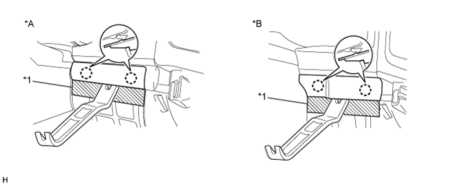
Text in Illustration *A w/ Entry and Start System *B w/o Entry and Start System *1 Protective Tape - -
| 11. REMOVE NO. 1 INSTRUMENT PANEL UNDER COVER SUB-ASSEMBLY (w/ Floor Under Cover) |
 |
Remove the 2 screws.
Detach the 3 claws.
Disconnect the connectors and remove the No. 1 instrument panel under cover.
| 12. REMOVE FRONT DOOR SCUFF PLATE LH |
 |
Detach the 7 claws and 4 clips, and remove the scuff plate.
| 13. REMOVE COWL SIDE TRIM BOARD LH |
 |
Remove the cap nut.
Detach the 2 clips and remove the cowl side trim board.
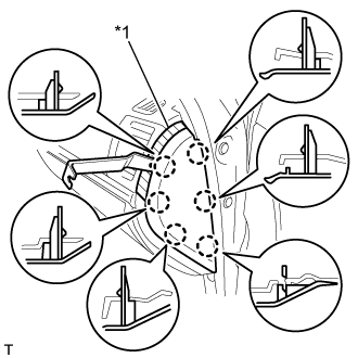
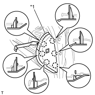
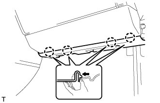
| 14. REMOVE LOWER NO. 1 INSTRUMENT PANEL FINISH PANEL |
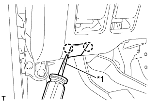 |
Using a screwdriver, detach the 2 claws and open the hole cover.
- HINT:
- Tape the screwdriver tip before use.
Text in Illustration *1 Protective Tape
w/ Driver Side Knee Airbag:
Remove the 2 bolts.
Detach the 16 claws.
w/o Driver Side Knee Airbag:
Remove the 2 bolts.
Detach the 9 claws.

for Automatic Air Conditioning System:
Detach the 2 claws and remove the room temperature sensor.
 |
Detach the 2 claws and disconnect the 2 control cables.
 |
Disconnect the connectors and remove the lower No. 1 instrument panel finish panel.
| 15. REMOVE NO. 1 SWITCH HOLE BASE |
 |
Detach the 4 claws.
Disconnect the connectors and remove the No. 1 switch hole cover.
| 16. REMOVE DRIVER SIDE KNEE AIRBAG ASSEMBLY (w/ Driver Side Knee Airbag) |
Remove the 5 bolts and driver side knee airbag.
 |
Disconnect the connector.
- NOTICE:
- When handling the airbag connector, take care not to damage the airbag wire harness.
| 17. REMOVE LOWER INSTRUMENT PANEL SUB-ASSEMBLY (w/o Driver Side Knee Airbag) |
 |
Detach the 2 claws and disconnect the DLC3.
Remove the 5 bolts and lower instrument panel.
| 18. REMOVE INSTRUMENT SIDE PANEL RH (w/o Airbag Cut Off Switch) |
 |
Place protective tape as shown in the illustration.
Text in Illustration *1 Protective Tape
Using a moulding remover, detach the 6 claws and remove the instrument side panel.
| 19. REMOVE INSTRUMENT SIDE PANEL RH (w/ Airbag Cut Off Switch) |
 |
Place protective tape as shown in the illustration.
Text in Illustration *1 Protective Tape
Using a moulding remover, detach the 6 claws.
Disconnect the connector and remove the instrument side panel.
| 20. REMOVE FRONT DOOR SCUFF PLATE RH |
- HINT:
- Use the same procedures described for the LH side.
| 21. REMOVE NO. 2 INSTRUMENT PANEL UNDER COVER SUB-ASSEMBLY (w/ Floor Under Cover) |
 |
Detach the 4 claws and remove the No. 2 instrument panel under cover.
| 22. REMOVE COWL SIDE TRIM BOARD RH |
 |
Remove the cap nut.
Detach the 2 clips and remove the cowl side trim board.
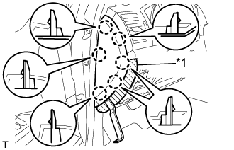
| 23. REMOVE FRONT PASSENGER SIDE KNEE AIRBAG ASSEMBLY (w/ Passenger Side Knee Airbag) |
Remove the 4 bolts.
 |
Detach the 4 claws and remove the front passenger side knee airbag.
Disconnect the connector.
- NOTICE:
- When handling the airbag connector, take care not to damage the airbag wire harness.
| 24. REMOVE LOWER INSTRUMENT PANEL (w/o Passenger Side Knee Airbag) |
 |
Remove the 2 bolts.
Detach the 4 claws and remove the lower instrument panel.
| 25. REMOVE NO. 3 INSTRUMENT CLUSTER FINISH PANEL GARNISH |
 |
Place protective tape as shown in the illustration.
Text in Illustration *1 Protective Tape
Using a moulding remover, detach the 6 claws and remove the No. 3 instrument cluster finish panel garnish.
| 26. REMOVE INSTRUMENT PANEL BOX DOOR KNOB |
 |
Using a moulding remover, detach the 2 claws and remove the instrument panel box door knob.
| 27. REMOVE LOWER NO. 2 INSTRUMENT PANEL FINISH PANEL |
 |
Remove the 4 bolts.
Detach the 3 claws.
Disconnect the connector and remove the lower No. 2 instrument panel finish panel.
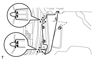
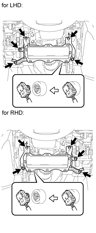
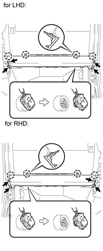
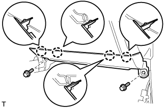
| 28. REMOVE STEERING CONTROL ECU WITH JUNCTION BLOCK (for LHD) |
Vehicle rear side:
Disconnect the 7 connectors.
Detach the 2 clamps.
Remove the bolt and 2 nuts.
 |
Vehicle front side:
Disconnect the 5 connectors.
Remove the steering control ECU with junction block from the vehicle.
| 29. REMOVE STEERING CONTROL ECU WITH JUNCTION BLOCK (for RHD) |
Vehicle rear side:
Disconnect the 2 connectors.
Remove the bolt and 2 nuts.
 |
Vehicle front side:
Disconnect the connector.
Remove the steering control ECU with junction block from the vehicle.
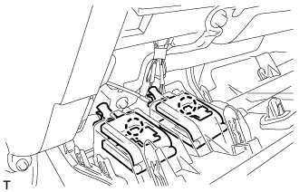
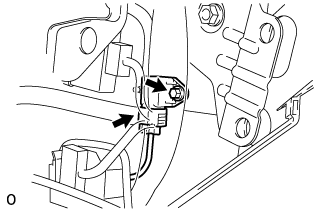
| 30. REMOVE ACCELERATION SENSOR (for Driver Side) |
Disconnect the connector.
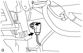 |
Remove the bolt and sensor.
- HINT:
- Use the same procedures for LHD and RHD vehicles.
| 31. REMOVE ACCELERATION SENSOR (for Front Passenger Side) |
Disconnect the connector.
 |
Remove the bolt and sensor.
- HINT:
- Use the same procedures for LHD and RHD vehicles.