Dtc C1791 Absorber Control Switch Circuit (Test Mode Dtc)
Suspension. Land Cruiser. Urj200, 202 Grj200 Vdj200
DESCRIPTION
WIRING DIAGRAM
INSPECTION PROCEDURE
READ VALUE USING INTELLIGENT TESTER (SPORT SWITCH, COMFORT SWITCH)
TEST MODE INSPECTION
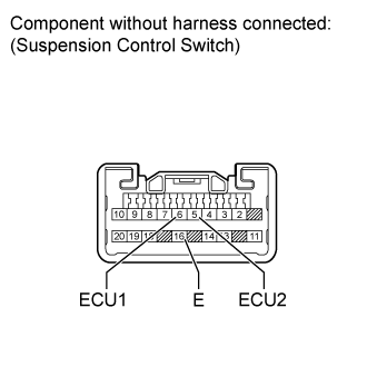
INSPECT SUSPENSION CONTROL SWITCH (DAMPING FORCE CONTROL SWITCH)
CHECK HARNESS AND CONNECTOR (SUSPENSION CONTROL ECU - SWITCH AND BODY GROUND)
DTC C1791 Absorber Control Switch Circuit (Test Mode DTC) |
DESCRIPTION
This circuit is used for sending the signal to the suspension control ECU to switch to the damping mode selected by the damping force control switch.DTC Code
| Detection Condition
| Trouble Area
|
C1791
| The test mode procedure is performed.
| - Harness or connector
- Suspension control switch (Damping forcer control switch)
- Suspension control ECU
|
WIRING DIAGRAM
INSPECTION PROCEDURE
- NOTICE:
- Before performing troubleshooting, inspect the connectors of related circuits.
- If the suspension control ECU or height control sensor is replaced, the vehicle height offset calibration must be performed (Click here).
| 1.READ VALUE USING INTELLIGENT TESTER (SPORT SWITCH, COMFORT SWITCH) |
Turn the engine switch off.
Connect the intelligent tester to the DLC3.
Turn the engine switch on (IG) and the tester on.
Enter the following menus: Chassis / AHC / Data List.
According to the display on the tester, read the Data List.
AHCTester Display
| Measurement Item/Range
| Normal Condition
| Diagnostic Note
|
SPORT Switch
| Damping force control switch (SPORT) /
ON or OFF
| ON: SPORT
OFF: NORMAL or COMFORT
| -
|
COMFORT Switch
| Damping force control switch (COMFORT) /
ON or OFF
| ON: COMFORT
OFF: NORMAL or SPORT
| -
|
- OK:
- On the tester screen, item changes between ON and OFF according to switch operation.
Refer to the Test Mode Procedure and perform the signal check. Check that test mode DTC C1791 is cleared (Click here).
ResultResult
| Proceed to
|
DTC C1791 is not cleared
| A
|
DTC C1791 is cleared
| B
|
| 3.INSPECT SUSPENSION CONTROL SWITCH (DAMPING FORCE CONTROL SWITCH) |
Remove the suspension control switch (Click here).
Measure the resistance according to the value(s) in the table below.
- Standard Resistance:
Tester Connection
| Switch Condition
| Specified Condition
|
5 (ECU2) - 16 (E)
| COMF
| Below 1 Ω
|
Except COMF
| 10 kΩ or higher
|
6 (ECU1) - 16 (E)
| SPORT
| Below 1 Ω
|
Except SPORT
| 10 kΩ or higher
|
| 4.CHECK HARNESS AND CONNECTOR (SUSPENSION CONTROL ECU - SWITCH AND BODY GROUND) |
Disconnect the K34 ECU connector.
Disconnect the V4 switch connector.
Measure the resistance according to the value(s) in the table below.
- Standard Resistance:
Tester Connection
| Condition
| Specified Condition
|
K34-2 (TSW1) - V4-6 (ECU1)
| Always
| Below 1 Ω
|
K34-2 (TSW1) - Body ground
| Always
| 10 kΩ or higher
|
K34-9 (TSW2) - V4-5 (ECU2)
| Always
| Below 1 Ω
|
K34-9 (TSW2) - Body ground
| Always
| 10 kΩ or higher
|
V4-16 (E) - Body ground
| Always
| Below 1 Ω
|
| | REPAIR OR REPLACE HARNESS OR CONNECTOR |
|
|