Rear Differential Carrier Assembly (For Standard) Disassembly
Drivetrain. Land Cruiser. Urj200, 202 Grj200 Vdj200
INSPECT RUNOUT OF REAR DRIVE PINION COMPANION FLANGE
INSPECT RUNOUT OF DIFFERENTIAL RING GEAR
INSPECT DIFFERENTIAL RING GEAR BACKLASH
REMOVE DRIVE PINION COMPANION FLANGE REAR NUT
REMOVE REAR DRIVE PINION COMPANION FLANGE REAR SUB-ASSEMBLY
REMOVE REAR DIFFERENTIAL CARRIER OIL SEAL
REMOVE REAR DIFFERENTIAL DRIVE PINION OIL SLINGER
REMOVE REAR DRIVE PINION FRONT TAPERED ROLLER BEARING
REMOVE REAR DIFFERENTIAL BEARING ADJUSTING NUT LOCK
REMOVE DIFFERENTIAL CASE ASSEMBLY
REMOVE DIFFERENTIAL DRIVE PINION
REMOVE REAR DIFFERENTIAL DRIVE PINION BEARING SPACER
REMOVE REAR DRIVE PINION REAR TAPERED ROLLER BEARING
REMOVE REAR DIFFERENTIAL DRIVE PINION PLATE WASHER
REMOVE REAR DRIVE PINION FRONT TAPERED ROLLER BEARING
REMOVE REAR DRIVE PINION REAR TAPERED ROLLER BEARING
REMOVE DIFFERENTIAL RING GEAR
INSPECT RUNOUT OF DIFFERENTIAL CASE
REMOVE REAR DIFFERENTIAL CASE BEARING
DISASSEMBLE DIFFERENTIAL CASE
Rear Differential Carrier Assembly (For Standard) -- Disassembly |
| 1. INSPECT RUNOUT OF REAR DRIVE PINION COMPANION FLANGE |
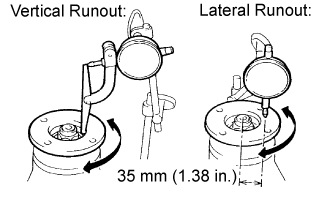
Using a dial indicator, measure the runout of the companion flange vertically and laterally.
- Maximum Runout:
Runout
| Specified Condition
|
Vertical runout
| 0.10 mm (0.00394 in.)
|
Lateral runout
| 0.10 mm (0.00394 in.)
|
If the runout is more than the maximum, replace the companion flange.
| 2. INSPECT RUNOUT OF DIFFERENTIAL RING GEAR |
Using a dial indicator, measure the ring gear runout.
- Maximum runout:
- 0.05 mm (0.00197 in.)
If the runout is more than the maximum, replace the ring gear.
| 3. INSPECT DIFFERENTIAL RING GEAR BACKLASH |
Using a dial indicator, measure the ring gear backlash.
- Standard backlash:
- 0.10 to 0.20 mm (0.00394 to 0.00787 in.)
- HINT:
- Measure at 3 or more positions around the circumference of the ring gear.
If the backlash is not as specified, adjust the side bearing preload or repair as necessary.
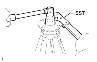
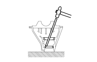
| 4. REMOVE DRIVE PINION COMPANION FLANGE REAR NUT |
Using SST and a hammer, unstake the nut.
- SST
- 09930-00010
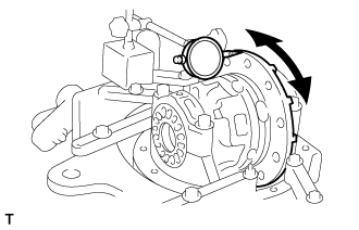
Using SST to hold the companion flange, remove the nut.
- SST
- 09330-00021(09330-00030)
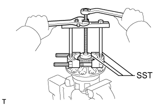
| 5. REMOVE REAR DRIVE PINION COMPANION FLANGE REAR SUB-ASSEMBLY |
Using SST, remove the companion flange.
- SST
- 09950-30012(09951-03010,09953-03010,09954-03010,09955-03030,09956-03040)
| 6. REMOVE REAR DIFFERENTIAL CARRIER OIL SEAL |
Using SST, remove the oil seal from the differential carrier.
- SST
- 09308-10010
| 7. REMOVE REAR DIFFERENTIAL DRIVE PINION OIL SLINGER |
| 8. REMOVE REAR DRIVE PINION FRONT TAPERED ROLLER BEARING |
Using SST, remove the front bearing (inner race) from the drive pinion.
- SST
- 09556-22010
If the front bearing is damaged or worn, replace the bearing.
| 9. REMOVE REAR DIFFERENTIAL BEARING ADJUSTING NUT LOCK |
Remove the 2 bolts and 2 adjusting nut locks.
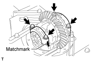
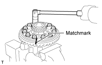
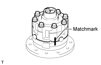
| 10. REMOVE DIFFERENTIAL CASE ASSEMBLY |
Place matchmarks on the bearing caps and differential carrier.
Remove the 4 bolts, 2 bearing caps, 2 adjusting nuts and 2 bearings (outer race).
Remove the differential case from the differential carrier.
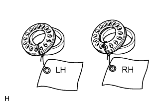
- HINT:
- Tag the 2 case bearing outer races to show the location for reassembly.
| 11. REMOVE DIFFERENTIAL DRIVE PINION |
Remove the differential drive pinion from the differential carrier.
| 12. REMOVE REAR DIFFERENTIAL DRIVE PINION BEARING SPACER |
| 13. REMOVE REAR DRIVE PINION REAR TAPERED ROLLER BEARING |
Using SST and a press, press out the bearing (inner race).
- SST
- 09950-00020
If either the drive pinion or ring gear is damaged, replace them as a set.
| 14. REMOVE REAR DIFFERENTIAL DRIVE PINION PLATE WASHER |
| 15. REMOVE REAR DRIVE PINION FRONT TAPERED ROLLER BEARING |
Using a brass bar and hammer, tap out the bearing (outer race).
| 16. REMOVE REAR DRIVE PINION REAR TAPERED ROLLER BEARING |
Using a brass bar and hammer, tap out the bearing (outer race).
| 17. REMOVE DIFFERENTIAL RING GEAR |
Place matchmarks on the ring gear and differential case.
Remove the 12 ring gear set bolts.
Using a plastic-faced hammer, tap on the ring gear to disconnect it from the differential case.
| 18. INSPECT RUNOUT OF DIFFERENTIAL CASE |
- HINT:
- If the ring gear runout is at the maximum or less (refer to the "Inspect Runout of Differential Ring Gear" procedure), this inspection is not necessary.
Install the differential case to the differential carrier.
Using a dial indicator, measure the differential case runout.
- Maximum runout:
- 0.04 mm (0.00157 in.)
If the runout is more than the maximum, replace the differential case and side bearings as a set.
Remove the differential case from the differential carrier.
| 19. REMOVE REAR DIFFERENTIAL CASE BEARING |
Using SST, remove the 2 side bearings (inner race) from the differential case.
- SST
- 09950-00020
09950-00030
09950-40011(09957-04010)
09950-60010(09951-00480)
| 20. DISASSEMBLE DIFFERENTIAL CASE |
Place matchmarks on the differential case LH and RH.
Remove the 8 bolts uniformly, a little at a time.
Using a plastic-faced hammer, disconnect the differential case LH and RH.
Remove the 2 side gear thrust washers, 2 side gears, spider, 4 pinion gears and 4 pinion gear thrust washers.