Land Cruiser URJ200 URJ202 GRJ200 VDJ200 - 3UR-FE ENGINE CONTROL
CHECK STOP LIGHT SWITCH ASSEMBLY (B+ VOLTAGE)
INSPECT STOP LIGHT SWITCH ASSEMBLY
CHECK ECM (STP AND ST1 - VOLTAGE)
DTC P0504 Brake Switch "A" / "B" Correlation
DESCRIPTION
The stop light switch is a duplex system that transmits two signals: STP and ST1-. These two signals are used by the ECM to monitor whether or not the brake system is working properly. If the signals, which indicate the brake pedal is being depressed and released, are detected simultaneously, the ECM interprets this as a malfunction in the stop light switch and stores the DTC.
- HINT:
- The normal signal conditions are as shown in the table below.
| Signal (ECM Terminal) | Brake Pedal Released | In Transition | Brake Pedal Depressed |
| STP | OFF | ON | ON |
| ST1- | ON | ON | OFF |
| DTC Code | DTC Detection Condition | Trouble Area |
| P0504 | Conditions (a), (b) and (c) continue for 0.5 seconds or more (1 trip detection logic): (a) The engine switch is on (IG). (b) The brake pedal is released. (c) The STP signal is OFF when the ST1- signal is OFF. | Short in stop light switch signal circuit STOP fuse IGN fuse Stop light switch ECM |
WIRING DIAGRAM

INSPECTION PROCEDURE
- NOTICE:
- Inspect the fuses for circuits related to this system before performing the following inspection procedure.
- HINT:
| Brake Pedal Operation | Stop Light Switch | ST1 |
| Depressed | ON | ON |
| Released | OFF | OFF |
| 1.CHECK STOP LIGHT SWITCH ASSEMBLY (B+ VOLTAGE) |
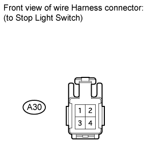
Disconnect the A30 stop light switch connector.
Measure the voltage according to the value(s) in the table below.
- Standard Voltage:
Tester Connection Switch Condition Specified Condition A30-2 - Body ground Always 11 to 14 V A30-4 - Body ground Engine switch on (IG) 11 to 14 V
|
| ||||
| OK | |
| 2.INSPECT STOP LIGHT SWITCH ASSEMBLY |
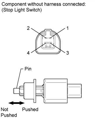
Remove the stop light switch.
Measure the resistance according to the value(s) in the table below.
- Standard Resistance:
Tester Connection Switch Condition Specified Condition 1 - 2 Pin not pushed Below 1 Ω Pin pushed 10 kΩ or higher 3 - 4 Pin not pushed 10 kΩ or higher Pin pushed Below 1 Ω
|
| ||||
| OK | |
| 3.CHECK ECM (STP AND ST1 - VOLTAGE) |
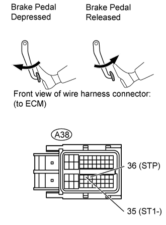
Disconnect the A38 ECM connector.
Turn the engine switch on (IG).
Measure the voltage according to the value(s) in the table below.
- Standard Voltage:
Tester Connection Condition Specified Condition A38-35 (ST1-) - Body ground Brake pedal released 11 to 14 V Brake pedal depressed 0 to 3 V A38-36 (STP) - Body ground Brake pedal released 0 to 3 V Brake pedal depressed 11 to 14 V
|
| ||||
| OK | ||
| ||